E3000 MPE/IX, E3000/IX specifications
The HP E3000 series, particularly the E3000/IX and E3000 MPE/IX, represents a significant milestone in the evolution of business computing, developed by Hewlett-Packard (HP) during the late 1970s and early 1980s. These systems were designed to provide robust, reliable, and efficient operation for mid-sized businesses, leveraging the power of the MPE (Multi-Programming Executive) operating system.One of the main features of the HP E3000 series is its multitasking capability. MPE/IX allows for multiple applications to run concurrently, maximizing the utilization of system resources. This is particularly beneficial for organizations that require simultaneous access to various business applications, ensuring enhanced productivity and efficiency.
The HP E3000/IX architecture is built on a powerful 16-bit or 32-bit microprocessor, enabling it to handle substantial workloads. The system architecture is known for its modular design, which allows for easy upgrades and customization. This flexibility is essential for businesses that need to adapt to changing demands without overhauling their entire computing infrastructure.
Another notable technology incorporated into the HP E3000 series is its support for a range of storage solutions. The E3000 systems were compatible with various disk drives, providing organizations with options for data storage that matched their performance and capacity requirements. Additionally, they featured advanced data management capabilities, such as built-in backup and recovery systems, ensuring that critical business information remained secure and accessible.
Beyond hardware capabilities, HP E3000/IX and MPE/IX systems provide extensive programming support. They included tools for developing custom applications, with support for languages such as COBOL, BASIC, and FORTRAN. This versatility made it easier for businesses to tailor their software solutions to their specific needs, enhancing operational effectiveness.
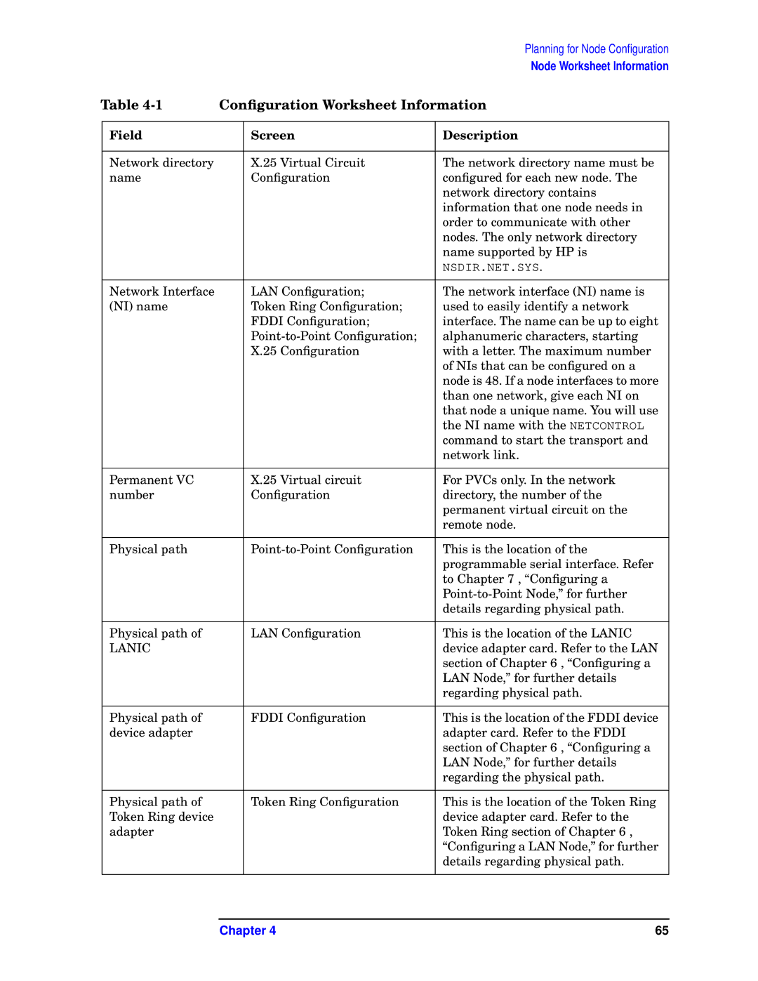
Networking capabilities were also a significant innovation of the E3000 series. The systems offered robust support for various networking protocols, allowing for seamless integration with other computing environments. This facilitated communication and collaboration within an organization, as well as with external partners and clients.
In summary, the HP E3000/IX and E3000 MPE/IX systems were pivotal in delivering reliable computing power to mid-sized enterprises. With their multitasking operating system, modular architecture, advanced data management, and programming support, these systems provided an adaptable and comprehensive solution for evolving business needs. The legacy of the E3000 series is evident in how it paved the way for modern enterprise computing, focusing on flexibility, scalability, and efficiency.

