5.Select a
6.Before handling the PCI cards, discharge any static buildup on your body by touching the metal case of the computer. Hold the edge and do not touch the components.
7.Position the board into the PCI slot you selected.
8.Secure the card in place at the rear panel of the system.
2.6Device Installation for Windows Systems
Once Windows 95/98/2000 has started, the Plug and Play function of Windows system will find the new NuDAQ/NuIPC cards. If this is the first time to install NuDAQ/NuIPC cards in your Windows system , you will be informed to input the device information source. Please refer to the “Software Installation Guide” for the steps of installing the device.
2.7Connectors Pin Assignment
The
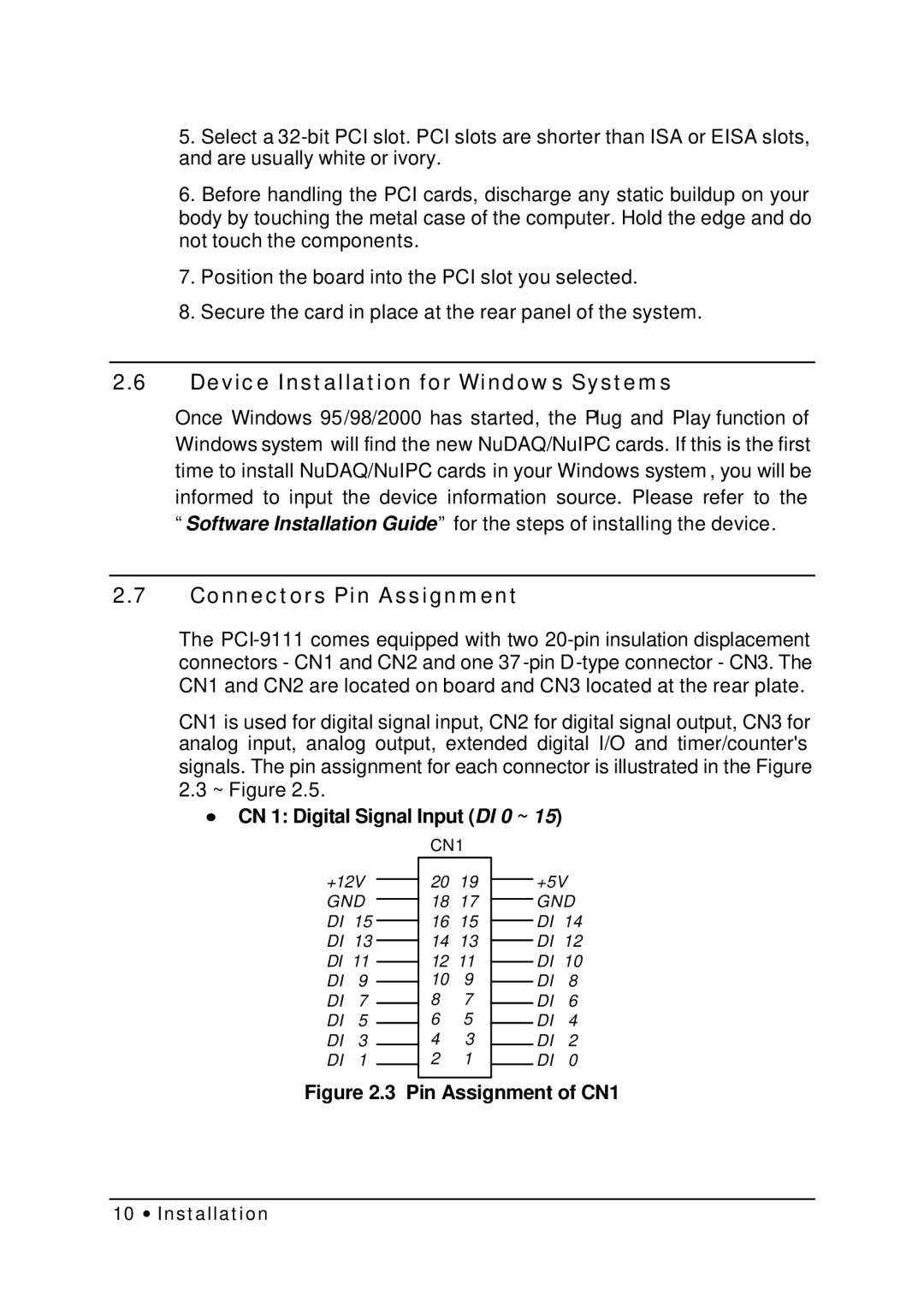
CN1 is used for digital signal input, CN2 for digital signal output, CN3 for analog input, analog output, extended digital I/O and timer/counter's signals. The pin assignment for each connector is illustrated in the Figure
2.3~ Figure 2.5.
∙CN 1: Digital Signal Input (DI 0 ~ 15)
+12V GND DI 15 DI 13 DI 11 DI 9 DI 7 DI 5 DI 3 DI 1
CN1
2019
1817
1615
1413
1211
109
87
65
43
21
+5V GND DI 14 DI 12 DI 10 DI 8 DI 6 DI 4 DI 2 DI 0
Figure 2.3 Pin Assignment of CN1
10 ∙ Installation