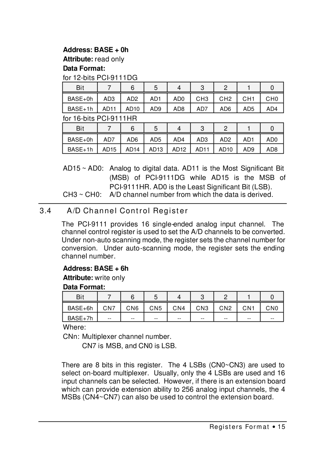
Address: BASE + 0h
Attribute: read only
Data Format:
for
Bit | 7 | 6 | 5 | 4 | 3 | 2 | 1 | 0 |
|
|
|
|
|
|
|
|
|
BASE+0h | AD3 | AD2 | AD1 | AD0 | CH3 | CH2 | CH1 | CH0 |
BASE+1h | AD11 | AD10 | AD9 | AD8 | AD7 | AD6 | AD5 | AD4 |
for |
|
|
|
|
|
| ||
Bit | 7 | 6 | 5 | 4 | 3 | 2 | 1 | 0 |
|
|
|
|
|
|
|
|
|
BASE+0h | AD7 | AD6 | AD5 | AD4 | AD3 | AD2 | AD1 | AD0 |
BASE+1h | AD15 | AD14 | AD13 | AD12 | AD11 | AD10 | AD9 | AD8 |
AD15 ~ AD0: Analog to digital data. AD11 is the Most Significant Bit (MSB) of
CH3 ~ CH0: A/D channel number from which the data is derived.
3.4A/D Channel Control Register
The
Address: BASE + 6h
Attribute: write only
Data Format:
Bit | 7 | 6 | 5 | 4 | 3 | 2 | 1 | 0 |
|
|
|
|
|
|
|
|
|
BASE+6h | CN7 | CN6 | CN5 | CN4 | CN3 | CN2 | CN1 | CN0 |
BASE+7h |
Where:
CNn: Multiplexer channel number.
CN7 is MSB, and CN0 is LSB.
There are 8 bits in this register. The 4 LSBs (CN0~CN3) are used to select