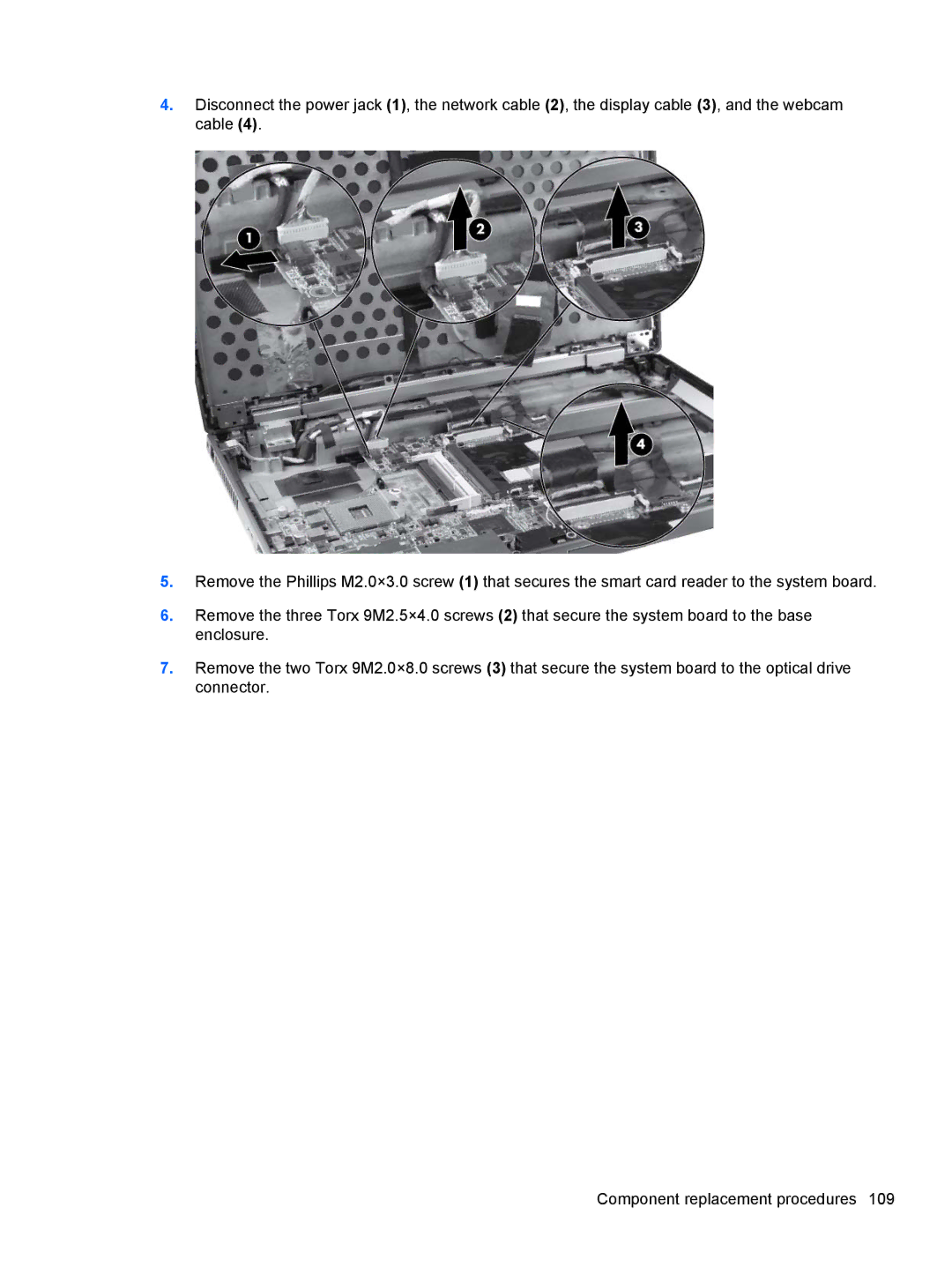
4.Disconnect the power jack (1), the network cable (2), the display cable (3), and the webcam cable (4).
5.Remove the Phillips M2.0×3.0 screw (1) that secures the smart card reader to the system board.
6.Remove the three Torx 9M2.5×4.0 screws (2) that secure the system board to the base enclosure.
7.Remove the two Torx 9M2.0×8.0 screws (3) that secure the system board to the optical drive connector.
Component replacement procedures 109