5.Remove the tape from along the back edge of the system board (4).
CAUTION: Support the display assembly when removing the display screws in the following steps. Failure to support the display assembly can result in damage to the assembly and other components.
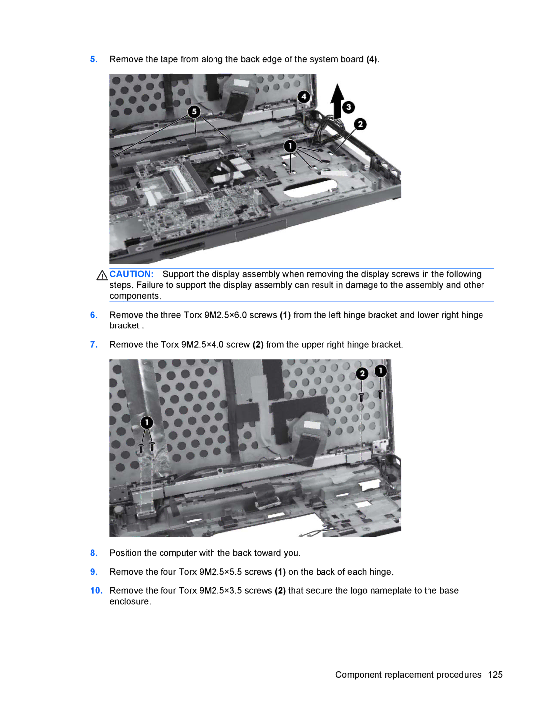
6.Remove the three Torx 9M2.5×6.0 screws (1) from the left hinge bracket and lower right hinge bracket .
7.Remove the Torx 9M2.5×4.0 screw (2) from the upper right hinge bracket.
8.Position the computer with the back toward you.
9.Remove the four Torx 9M2.5×5.5 screws (1) on the back of each hinge.
10.Remove the four Torx 9M2.5×3.5 screws (2) that secure the logo nameplate to the base enclosure.
Component replacement procedures 125