•“1070 Keyboard” on page 85
•“1100 Palm rest or palm rest with fingerprint reader” on page 91
•“1110 Bluetooth daughter card
•“1120 Keyboard bezel and speaker assembly” on page 94
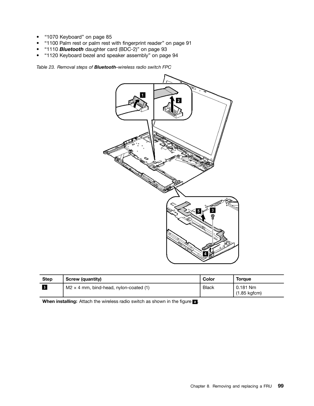
Table 23. Removal steps of Bluetooth–wireless radio switch FPC
| Step | Screw (quantity) | Color | Torque | |
|
|
|
|
|
|
|
|
| M2 × 4 mm, | Black | 0.181 Nm |
| 3 |
| |||
|
|
|
|
| (1.85 kgfcm) |
|
|
|
|
|
|
When installing: Attach the wireless radio switch as shown in the figure ![]()
![]() .
.
Chapter 8. Removing and replacing a FRU 99