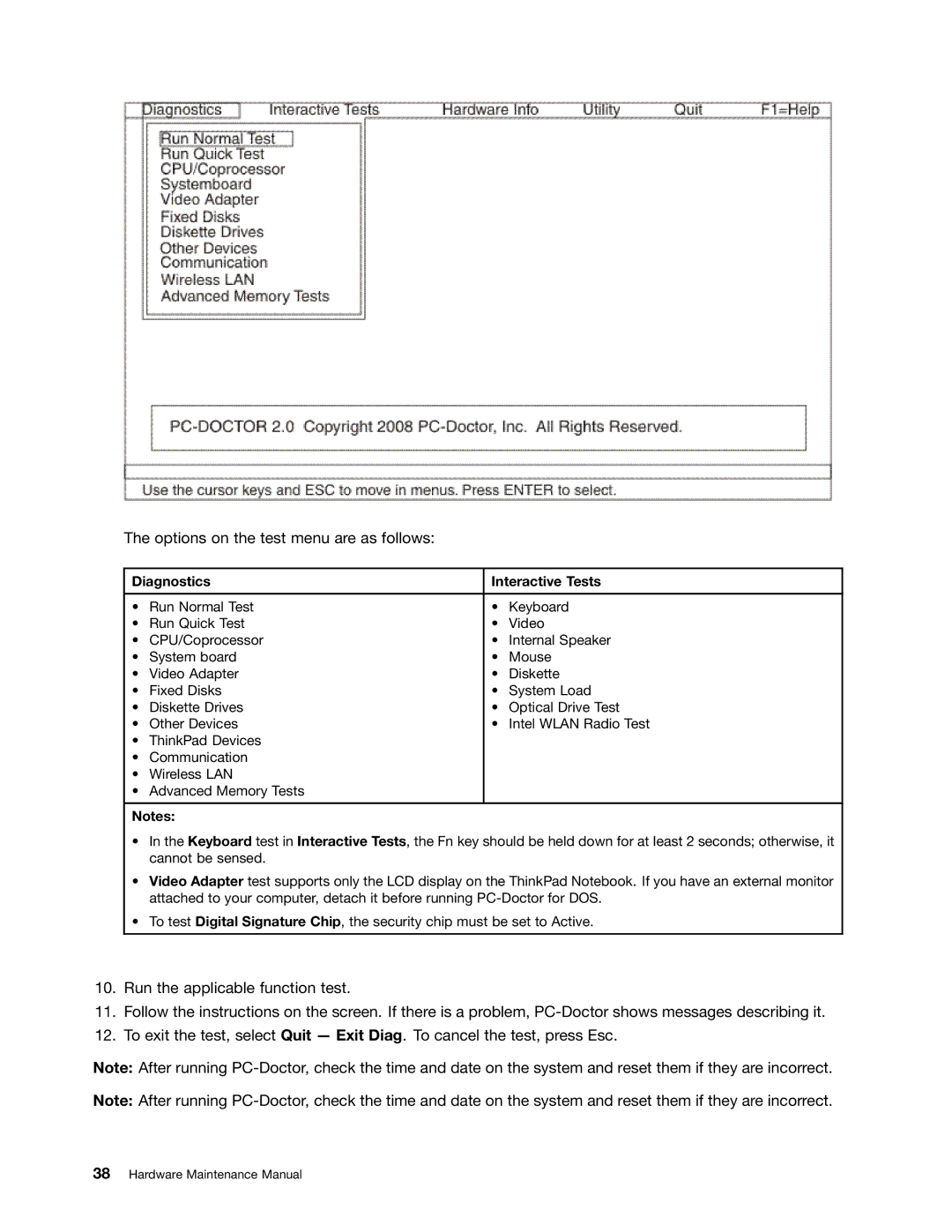
Hardware Maintenance Manual
ThinkPad T400s, T410s, and T410si
Page
Contents
Chapter 9. Locations
Chapter 10. Parts list
ii Hardware Maintenance Manual
About this manual
iv Hardware Maintenance Manual
Chapter 1. Safety information
General safety
Electrical safety
Safety inspection guide
Handling devices that are sensitive to electrostatic discharge
Safety notices multilingual translations
Grounding requirements
DANGER
DANGER
DANGER
DANGER
DANGER
DANGER
6 Hardware Maintenance Manual
DANGER
Chapter 1. Safety information
8 Hardware Maintenance Manual
PERIGO
PERIGO
PERIGO
PERIGO
PERIGO
PERIGO
PERIGO
DANGER
DANGER
DANGER
DANGER
DANGER
DANGER
VORSICHT
VORSICHT
VORSICHT
VORSICHT
VORSICHT
VORSICHT
Chapter 1. Safety information
14 Hardware Maintenance Manual
Chapter 1. Safety information
16 Hardware Maintenance Manual
Chapter 1. Safety information
18 Hardware Maintenance Manual
La batería de repuesto es una batería de litio y puede provocar incendios, explosiones o quemaduras graves. No la recargue, ni quite el conector polarizado, ni la desmonte, ni caliente por encima de los 100C 212F, ni la incinere ni exponga el contenido de sus celdas al agua. Deséchela tal como dispone la normativa local
20 Hardware Maintenance Manual
Laser compliance statement multilingual translations
22 Hardware Maintenance Manual
DANGER
separadamente como opcionais. Se uma dessas unidades estiver instalada, ela é certificada nos Estados Unidos em conformidade com os requisitos do Department of Health and Human Services 21 Code of Federal Regulations DHHS 21 CFR, Subcapítulo J, para produtos a laser da Classe 1. Em outros países, a unidade é certificada em conformidade com os requisitos da International Electrotechnical Commission IEC 60825-1 e CENELEC EN 60825-1 para produtos a laser da Classe
PERIGO
GEFAHR
24 Hardware Maintenance Manual
DANGER
Chapter 1. Safety information
26 Hardware Maintenance Manual
Algunos modelos de sistemas ThinkPad están equipados de fábrica con un dispositivo de almacenamiento óptico, como una unidad de CD-ROM o de DVD-ROM. Estas unidades también se venden por separado como opciones. Si está instalada alguna de dichas unidades, se certifica que en los Estados Unidos cumple los requisitos del Department of Health and Human Services 21 Code of Federal Regulations DHHS 21 CFR Subchapter J para productos láser de Clase 1. En otros países, se certifica que cumple los requisitos para productos láser de Clase 1 de las normativas 60825-1 y CENELEC EN 60825-1 de International Electrotechnical Commission IEC
28 Hardware Maintenance Manual
PELIGRO
Chapter 1. Safety information
30 Hardware Maintenance Manual
Chapter 2. Important service information
Strategy for replacing FRUs
Before replacing parts
3. Select Downloads and drivers
How to use error message
Strategy for replacing a hard disk drive
Important notice for replacing a system board
Strategy for replacing FRUs for CTO, CMV, and GAV Product definition
FRU identification for CTO, CMV, and GAV products
Using PEW
Using eSupport
General Announce Variant GAV
Using the HMM
34 Hardware Maintenance Manual
Chapter 3. General checkout
What to do first
Only certified trained personnel should service the computer
When you replace FRUs, use new nylon-coated screws
The following are not covered under warranty
Diagnostics using PC-Doctor for DOS
Checkout guide
Testing the computer
Interactive Tests
Diagnostics
38 Hardware Maintenance Manual
Lenovo ThinkVantage Toolbox Lenovo System Toolbox
Detecting system information with PC-Doctor
Click Start → All Programs → Lenovo Services → Lenovo System Toolbox
Windows
PC-Doctor for Rescue and Recovery
FRU tests
Power system checkout
Checking the AC adapter
Checking the battery pack
Checking operational charging
Checking the backup battery
44 Hardware Maintenance Manual
Restoring the factory contents by using Recovery Disc Set
Chapter 4. Related service information
Restoring the factory contents by using Product Recovery discs
Operating System Recovery Disc one disc
Applications and Drivers Recovery Disc one or more discs
Supplemental Recovery Disc
2. Insert the Operating System Recovery Disc into the DVD drive
Passwords
Power-on password
Hard-disk password
Supervisor password
How to remove the hard-disk password
Power management
B If an SVP has been set and is known by the service technician
5. Select Power-On Password
Hibernation mode
Screen blank mode
Sleep standby mode
Symptom-to-FRU index
Numeric error codes
Table 2. Numeric error codes
Table 2. Numeric error codes continued
52 Hardware Maintenance Manual
Table 2. Numeric error codes continued
Symptom or error
Table 2. Numeric error codes continued
Unauthorized Wireless USB card is plugged in-Power off
Security Predesktop Area Access Predesktop
54 Hardware Maintenance Manual
Table 3. Error messages
Error messages
Table 2. Numeric error codes continued
Table 4. Beep symptoms
Beep symptoms
Table 3. Error messages continued
No-beep symptoms
LCD-related symptoms
Table 4. Beep symptoms continued
Table 5. No-beep symptoms
Table 6. LCD-related symptoms
Intermittent problems
Undetermined problems
Chapter 4. Related service information
5. Determine whether the problem has been solved
a. System board b. LCD assembly
60 Hardware Maintenance Manual
Chapter 5. Status indicators
Copyright Lenovo
Status indicators
Indicator
microphone mute is on by default
Wireless LAN
Meaning
Table 7. Status indicators continued
Indicator
Table 7. Status indicators continued
Indicator
64 Hardware Maintenance Manual
Meaning
Chapter 6. Fn key combinations
Table 8. Fn key combinations
Key combination
Description
66 Hardware Maintenance Manual
Table 8. Fn key combinations continued
Fn+Pause
Has the same function as the Break key
Fn+cursor keys
68 Hardware Maintenance Manual
External CRU statement to customers
Chapter 7. FRU replacement notices
Screw notices
3. Select 2. Read S/N data from EEPROM
Retaining serial numbers
Restoring the serial number of the system unit
Chapter 7. FRU replacement notices
Retaining the UUID
Reading or writing the ECA information
72 Hardware Maintenance Manual
DANGER
Chapter 8. Removing and replacing a FRU
External CRU statement to customers
Removing the SIM card
Before servicing ThinkPad T400s, T410s, and T410si
Notice on disconnecting the cable from flip-lock ZIF connector
Important notice for replacing a battery pack
1010 Battery pack
1020 Serial Ultrabay Slim device or travel bezel
1030 Solid state drive SSD or hard disk drive HDD
“1010 Battery pack” on page
For access, remove these FRUs in order “1010 Battery pack” on page
76 Hardware Maintenance Manual
Table 11. Removal steps of SSD or HDD
Step
Screw quantity
Color
1040 DIMM
78 Hardware Maintenance Manual
Table 11. Removal steps of SSD or HDD continued
Table 12. Removal steps of DIMM
Chapter 8. Removing and replacing a FRU
Table 12. Removal steps of DIMM continued
For ThinkPad T400s
1050 PCI Express Mini Card for wireless LAN
Table 13. Removal steps of PCI Express Mini Card for wireless LAN
Table 12. Removal steps of DIMM continued
For ThinkPad T410s and T410si
Note Some models might have only two antenna cables in step
Chapter 8. Removing and replacing a FRU
82 Hardware Maintenance Manual
Step
Screw quantity
Color
Table 14. Removal steps of PCI Express Mini Card for wireless WAN
1060 PCI Express Mini Card for wireless WAN
For access, remove these FRUs in order 1010 Battery pack
84 Hardware Maintenance Manual
Table 15. Removal steps of keyboard
1070 Keyboard
For access, remove these FRUs in order “1010 Battery pack” on page
86 Hardware Maintenance Manual
Table 15. Removal steps of keyboard continued
When installing the keyboard, do as follows
6 , and then detach the connector
Table 15. Removal steps of keyboard continued
Lift the keyboard a little in the direction shown by arrow
88 Hardware Maintenance Manual
DANGER
1080 Backup battery
Table 16. Installation steps of keyboard continued
90 Hardware Maintenance Manual
1090 Wireless USB adapter or Intel Turbo Memory
Table 17. Removal steps of backup battery
1100 Palm rest or palm rest with fingerprint reader
Table 18. Removal steps of wireless USB adapter or Intel Turbo Memory
92 Hardware Maintenance Manual
Chapter 8. Removing and replacing a FRU
1110 Bluetooth daughter card BDC-2
Table 20. Removal steps of BDC-2
Table 20. Removal steps of BDC-2 continued
1120 Keyboard bezel and speaker assembly
Table 21. Removal steps of keyboard bezel and speaker assembly
Step
Screw quantity
Color
Torque
96 Hardware Maintenance Manual
Note Before step
For ThinkPad T400s
Table 22. Removal steps of 5-in-1 Media Card Reader adapter
1140 Bluetooth-wireless radio switch FPC
1130 5-in-1 Media Card Reader adapter
“1110 Bluetooth daughter card BDC-2” on page
“1120 Keyboard bezel and speaker assembly” on page
Table 23. Removal steps of Bluetooth-wireless radio switch FPC
“1070 Keyboard” on page
1150 LCD unit
Table 24. Removal steps of LCD unit
When installing
Table 24. Removal steps of LCD unit continued
Step
Screw cap
Table 24. Removal steps of LCD unit continued
When installing Make sure that the connector is attached firmly
102 Hardware Maintenance Manual
1160 System board, fan assembly, and 34-mm ExpressCard slot frame
Important notices for handling the system board
d Accelerometer chip for the HDD Active Protection System
104 Hardware Maintenance Manual
ICH I/O Controller Hub b CPU GMCH Graphics Memory Controller Hub
d Graphic controller only for switchable graphics models
PCH Platform Controller Hub b CPU
Accelerometer chip for the HDD Active Protection System
Chapter 8. Removing and replacing a FRU
106 Hardware Maintenance Manual
8 to
108 Hardware Maintenance Manual
For ThinkPad T400s
Step
Screw quantity
Color
1170 I/O sub card and base cover assembly
110 Hardware Maintenance Manual
Table 26. Removal steps of I/O sub card and base cover assembly
2010 LCD bezel assembly
Chapter 8. Removing and replacing a FRU
Table 27. Removal steps of LCD bezel assembly
M2 × 3 mm, shoulder-socket head, nylon-coated
2020 LCD latch L and R
2030 Integrated camera or microphone sub card
114 Hardware Maintenance Manual
Table 28. Removal steps of LCD latch L and R
Table 29. Removal steps of integrated camera or microphone sub card
Step
Screw quantity
Color
Table 30. Removal steps of LED sub card
2040 LED sub card
116 Hardware Maintenance Manual
Table 30. Removal steps of LED sub card continued
Step
Screw quantity
Color
Table 30. Removal steps of LED sub card continued
2050 LCD panel
118 Hardware Maintenance Manual
DO NOT apply any kind of pressure to the LCD panel
2060 LCD cable
2070 Hinge kit
Table 32. Removal steps of LCD cable
122 Hardware Maintenance Manual
Table 33. Removal steps of hinge kit
2080 LED cable
Table 33. Removal steps of hinge kit continued
2090 Antenna kit and LCD rear cover assembly
Table 34. Removal steps of LED cable
Table 35. Removal steps of antenna kit and LCD rear cover assembly
126 Hardware Maintenance Manual
Chapter 9. Locations
Front view
Rear view
Universal serial bus USB connectors DisplayPort
USB/eSATA combo connector RJ-45 Ethernet connector
External monitor connector AC power connector
Bottom view
Solid state drive SSD or hard disk drive HDD Battery pack
Battery pack latch LCD cover latch Ultrabay Slim Media Bay lock latch
Ultrabay Slim Media Bay eject latch
130 Hardware Maintenance Manual
Chapter 10. Parts list
External CRU statement to customers
Overall
Table 36. Parts list-Overall
Keyboard bezel assembly
Speaker assembly
FRU no
Table 36. Parts list-Overall continued
FRU Overall
Table 36. Parts list-Overall continued
134 Hardware Maintenance Manual
FRU Overall
FRU no
FRU no
Table 36. Parts list-Overall continued
FRU Overall
Table 36. Parts list-Overall continued
136 Hardware Maintenance Manual
FRU Overall
FRU no
FRU no
Table 36. Parts list-Overall continued
FRU Overall
Table 36. Parts list-Overall continued
138 Hardware Maintenance Manual
FRU Overall
FRU no
Table 36. Parts list-Overall continued
FRU Overall
FRU no
DVD-RAM/RW drive
Table 36. Parts list-Overall continued
140 Hardware Maintenance Manual
FRU Overall
FRU no
FRU no
Table 36. Parts list-Overall continued
FRU Overall
Table 36. Parts list-Overall continued
142 Hardware Maintenance Manual
FRU Overall
FRU no
FRU no
Table 36. Parts list-Overall continued
FRU Overall
Table 36. Parts list-Overall continued
144 Hardware Maintenance Manual
FRU Overall
FRU no
FRU no
Table 36. Parts list-Overall continued
FRU Overall
Table 36. Parts list-Overall continued
146 Hardware Maintenance Manual
FRU Overall
FRU no
FRU no
Table 36. Parts list-Overall continued
FRU Overall
Table 36. Parts list-Overall continued
148 Hardware Maintenance Manual
FRU Overall
FRU no
FRU no
Table 36. Parts list-Overall continued
FRU Overall
Table 36. Parts list-Overall continued
150 Hardware Maintenance Manual
FRU Overall
FRU no
FRU no
Table 36. Parts list-Overall continued
FRU Overall
Table 36. Parts list-Overall continued
152 Hardware Maintenance Manual
FRU Overall
FRU no
FRU no
Table 36. Parts list-Overall continued
FRU Overall
Table 36. Parts list-Overall continued
154 Hardware Maintenance Manual
FRU Overall
FRU no
FRU no
Table 36. Parts list-Overall continued
FRU Overall
Table 36. Parts list-Overall continued
156 Hardware Maintenance Manual
FRU Overall
FRU no
FRU no
Table 36. Parts list-Overall continued
FRU Overall
Table 36. Parts list-Overall continued
158 Hardware Maintenance Manual
FRU Overall
FRU no
FRU no
Table 36. Parts list-Overall continued
FRU Overall
LCD FRUs
160 Hardware Maintenance Manual
Table 37. Parts list-14.1-inch WXGA+ LED-backlight LCD
Chapter 10. Parts list
FRU 14.1-inch WXGA+ LED-backlight LCD
FRU no
Table 37. Parts list-14.1-inch WXGA+ LED-backlight LCD continued
162 Hardware Maintenance Manual
Table 37. Parts list-14.1-inch WXGA+ LED-backlight LCD continued
FRU 14.1-inch WXGA+ LED-backlight LCD
FRU no
Integrated camera
Table 37. Parts list-14.1-inch WXGA+ LED-backlight LCD continued
164 Hardware Maintenance Manual
FRU 14.1-inch WXGA+ LED-backlight LCD
FRU no
Table 37. Parts list-14.1-inch WXGA+ LED-backlight LCD continued
FRU 14.1-inch WXGA+ LED-backlight LCD
FRU no
Hinge kit
Table 37. Parts list-14.1-inch WXGA+ LED-backlight LCD continued
LCD rear cover assembly
166 Hardware Maintenance Manual
FRU 14.1-inch WXGA+ LED-backlight LCD
Table 37. Parts list-14.1-inch WXGA+ LED-backlight LCD continued
FRU 14.1-inch WXGA+ LED-backlight LCD
FRU no
LED sub card
Table 37. Parts list-14.1-inch WXGA+ LED-backlight LCD continued
168 Hardware Maintenance Manual
FRU 14.1-inch WXGA+ LED-backlight LCD
FRU no
Table 37. Parts list-14.1-inch WXGA+ LED-backlight LCD continued
LED cable assembly
FRU 14.1-inch WXGA+ LED-backlight LCD
FRU no
170 Hardware Maintenance Manual
Table 37. Parts list-14.1-inch WXGA+ LED-backlight LCD continued
Table 38. Parts list-14.1-inch WXGA+ LED-backlight Multi touch panel
FRU 14.1-inch WXGA+ LED-backlight Multi touch panel
FRU no
FRU no
172 Hardware Maintenance Manual
FRU 14.1-inch WXGA+ LED-backlight Multi touch panel
FRU no
174 Hardware Maintenance Manual
Keyboard
Table 39. Parts list-Keyboard
Table 40. Parts list-Miscellaneous parts
Miscellaneous parts
Table 39. Parts list-Keyboard continued
Table 40. Parts list-Miscellaneous parts continued
176 Hardware Maintenance Manual
Table 40. Parts list-Miscellaneous parts continued
FRU no
Power cords
AC adapters
Table 41. Parts list-2-pin AC adapters
Table 42. Parts list-3-pin AC adapters
Recovery discs Windows XP Professional 32 bit DVDs
2809-CTO, 76x, 79x, 7Ex
Windows Vista Starter Edition 32 bit DVDs
Table 47. Parts list-Windows XP Professional 32 bit recovery DVDs
2924-CTO 2926-CTO 2928-CTO
2801-CTO 2808-CTO 2809-CTO 2815-CTO 2823-CTO 2824-CTO 2825-CTO
Windows Vista Home Basic 32 bit DVDs
Table 49. Parts list-Windows Vista Home Basic 32 bit recovery DVDs
Windows Vista Home Premium 32 bit DVDs
Table 50. Parts list-Windows Vista Home Premium 32 bit recovery DVDs
2801-CTO, A9x, AHx, AJx, AKx, ANx, APx 2808-CTO 2809-CTO 2815-CTO
2823-CTO 2824-CTO 2825-CTO
Windows Vista Business 32 bit DVDs
Windows Vista Business 64 bit DVDs
Windows Vista Ultimate 32 bit DVDs
Table 53. Parts list-Windows Vista Business 64 bit recovery DVDs
Table 54. Parts list-Windows Vista Ultimate 32 bit recovery DVDs
2801-CTO 2808-CTO 2809-CTO 2815-CTO, 2Qx, 2Tx, 3Nx, 3Qx
Windows 7 Home Basic 32 bit DVDs
Windows 7 Home Premium 32 bit DVDs
Table 56. Parts list-Windows 7 Home Basic 32 bit recovery DVDs
Table 57. Parts list-Windows 7 Home Premium 32 bit recovery DVDs
2928-CTO
Table 58. Parts list-Windows 7 Home Premium 32 bit recovery DVDs
2901-CTO, A7x, AAx 2904-CTO, CPx, CQx, CRx, CSx, F5x, G3x
2907-CTO, 75x 2912-CTO, 2Xx, 2Yx, 2Zx, 32x, 33x 2924-CTO 2926-CTO
2928-CTO
Windows 7 Home Premium 64 bit DVDs
Windows 7 Professional 32 bit DVDs
Table 60. Parts list-Windows 7 Home Premium 64 bit recovery DVDs
2901-CTO, A2x, ADx, AFx, AHx, AJx, AKx
2926-CTO 2928-CTO
Windows 7 Professional 64 bit DVDs
Table 63. Parts list-Windows 7 Professional 64 bit recovery DVDs
Table 65. Parts list-Common service tools
Common service tools
Table 64. Parts list-Windows 7 Professional 64 bit recovery DVDs
Table 65. Parts list-Common service tools continued
Removal tool antenna RF connector USB 2.0 CD-RW/DVD-ROM combo drive
Morrisville, NC U.S.A Attention Lenovo Director of Licensing
Notices
Lenovo United States, Inc 1009 Think Place - Building One
Trademarks
Page
45M227104
Part Number 45M227104 Printed in 1P P/N 45M227104