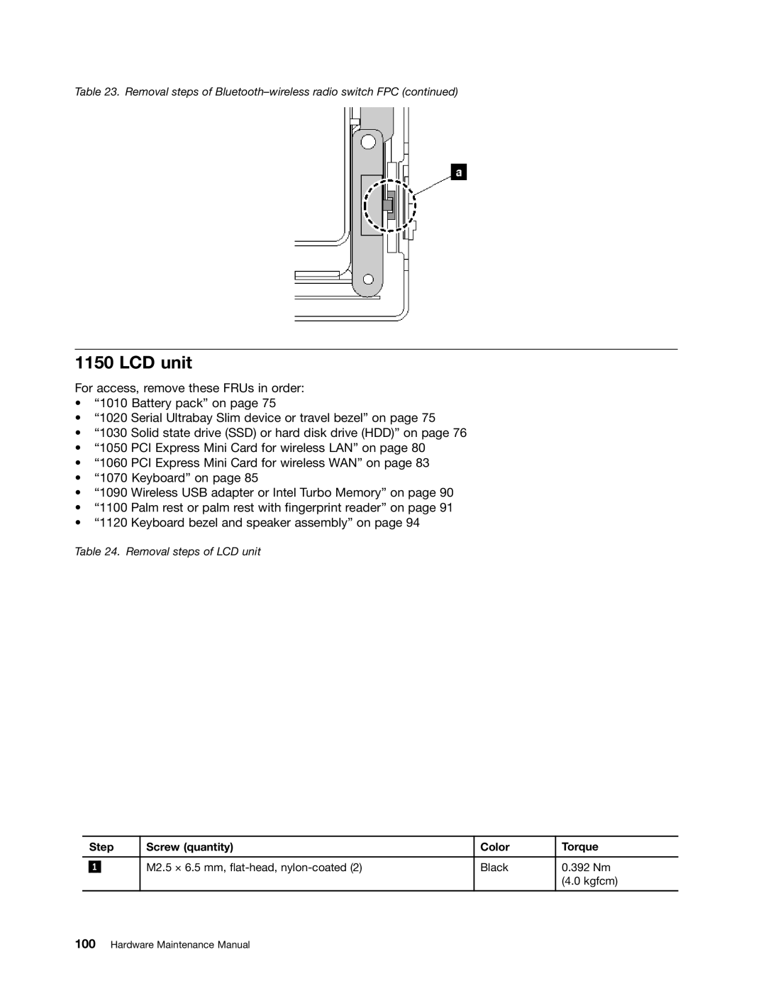
Table 23. Removal steps of Bluetooth–wireless radio switch FPC (continued)
1150 LCD unit
For access, remove these FRUs in order:
•“1010 Battery pack” on page 75
•“1020 Serial Ultrabay Slim device or travel bezel” on page 75
•“1030 Solid state drive (SSD) or hard disk drive (HDD)” on page 76
•“1050 PCI Express Mini Card for wireless LAN” on page 80
•“1060 PCI Express Mini Card for wireless WAN” on page 83
•“1070 Keyboard” on page 85
•“1090 Wireless USB adapter or Intel Turbo Memory” on page 90
•“1100 Palm rest or palm rest with fingerprint reader” on page 91
•“1120 Keyboard bezel and speaker assembly” on page 94
Table 24. Removal steps of LCD unit
| Step | Screw (quantity) | Color | Torque | |
|
|
|
|
|
|
|
|
| M2.5 × 6.5 mm, | Black | 0.392 Nm |
| 1 |
| |||
|
|
|
|
| (4.0 kgfcm) |
|
|
|
|
|
|