Table 20. Removal steps of
1
M2 × 4 mm,
Black
0.181 Nm
(1.85 kgfcm)
When installing: Make sure that the connector is attached firmly.
1120 Keyboard bezel and speaker assembly
For access, remove these FRUs in order:
•“1010 Battery pack” on page 75
•“1020 Serial Ultrabay Slim device or travel bezel” on page 75
•“1030 Solid state drive (SSD) or hard disk drive (HDD)” on page 76
•“1070 Keyboard” on page 85
•“1100 Palm rest or palm rest with fingerprint reader” on page 91
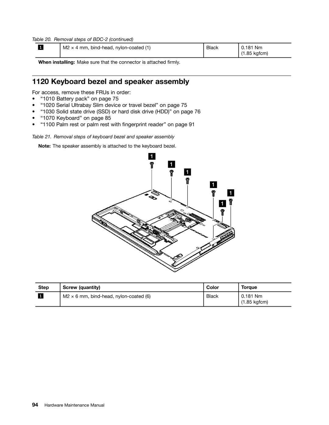
Table 21. Removal steps of keyboard bezel and speaker assembly
Note: The speaker assembly is attached to the keyboard bezel.
| Step | Screw (quantity) | Color | Torque | |
|
|
|
|
|
|
|
|
| M2 × 6 mm, | Black | 0.181 Nm |
| 1 |
| |||
|
|
|
|
| (1.85 kgfcm) |
|
|
|
|
|
|