FRU | FRU no. | CRU |
| | ID |
| | |
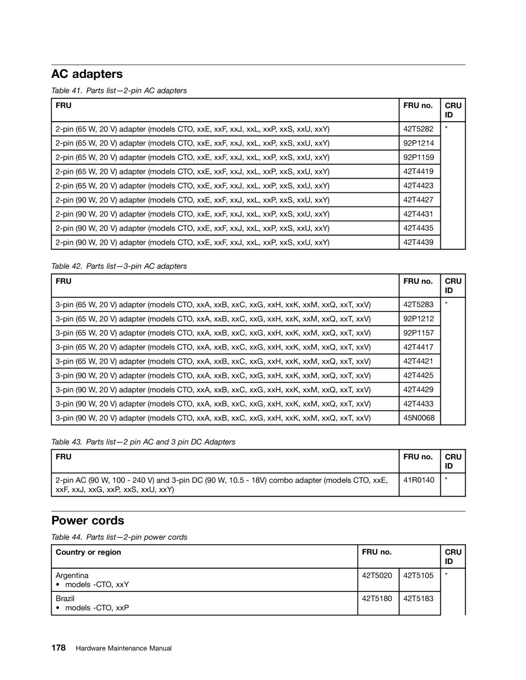
2-pin (65 W, 20 V) adapter (models CTO, xxE, xxF, xxJ, xxL, xxP, xxS, xxU, xxY) | 42T5282 | * |
| | |
2-pin (65 W, 20 V) adapter (models CTO, xxE, xxF, xxJ, xxL, xxP, xxS, xxU, xxY) | 92P1214 | |
| | |
2-pin (65 W, 20 V) adapter (models CTO, xxE, xxF, xxJ, xxL, xxP, xxS, xxU, xxY) | 92P1159 | |
| | |
2-pin (65 W, 20 V) adapter (models CTO, xxE, xxF, xxJ, xxL, xxP, xxS, xxU, xxY) | 42T4419 | |
| | |
2-pin (65 W, 20 V) adapter (models CTO, xxE, xxF, xxJ, xxL, xxP, xxS, xxU, xxY) | 42T4423 | |
| | |
2-pin (90 W, 20 V) adapter (models CTO, xxE, xxF, xxJ, xxL, xxP, xxS, xxU, xxY) | 42T4427 | |
| | |
2-pin (90 W, 20 V) adapter (models CTO, xxE, xxF, xxJ, xxL, xxP, xxS, xxU, xxY) | 42T4431 | |
| | |
2-pin (90 W, 20 V) adapter (models CTO, xxE, xxF, xxJ, xxL, xxP, xxS, xxU, xxY) | 42T4435 | |
| | |
2-pin (90 W, 20 V) adapter (models CTO, xxE, xxF, xxJ, xxL, xxP, xxS, xxU, xxY) | 42T4439 | |
| | |
Table 42. Parts list—3-pin AC adapters | | |
| | |
FRU | FRU no. | CRU |
| | ID |
| | |
3-pin (65 W, 20 V) adapter (models CTO, xxA, xxB, xxC, xxG, xxH, xxK, xxM, xxQ, xxT, xxV) | 42T5283 | * |
| | |
3-pin (65 W, 20 V) adapter (models CTO, xxA, xxB, xxC, xxG, xxH, xxK, xxM, xxQ, xxT, xxV) | 92P1212 | |
| | |
3-pin (65 W, 20 V) adapter (models CTO, xxA, xxB, xxC, xxG, xxH, xxK, xxM, xxQ, xxT, xxV) | 92P1157 | |
| | |
3-pin (65 W, 20 V) adapter (models CTO, xxA, xxB, xxC, xxG, xxH, xxK, xxM, xxQ, xxT, xxV) | 42T4417 | |
| | |
3-pin (65 W, 20 V) adapter (models CTO, xxA, xxB, xxC, xxG, xxH, xxK, xxM, xxQ, xxT, xxV) | 42T4421 | |
| | |
3-pin (90 W, 20 V) adapter (models CTO, xxA, xxB, xxC, xxG, xxH, xxK, xxM, xxQ, xxT, xxV) | 42T4425 | |
| | |
3-pin (90 W, 20 V) adapter (models CTO, xxA, xxB, xxC, xxG, xxH, xxK, xxM, xxQ, xxT, xxV) | 42T4429 | |
| | |
3-pin (90 W, 20 V) adapter (models CTO, xxA, xxB, xxC, xxG, xxH, xxK, xxM, xxQ, xxT, xxV) | 42T4433 | |
| | |
3-pin (90 W, 20 V) adapter (models CTO, xxA, xxB, xxC, xxG, xxH, xxK, xxM, xxQ, xxT, xxV) | 45N0068 | |
| | |
Table 43. Parts list—2 pin AC and 3 pin DC Adapters | | |
| | |
FRU | FRU no. | CRU |
| | ID |
| | |
2-pin AC (90 W, 100 - 240 V) and 3-pin DC (90 W, 10.5 - 18V) combo adapter (models CTO, xxE, | 41R0140 | * |
xxF, xxJ, xxG, xxP, xxS, xxU, xxY) | | |
| | |