•“1120 Keyboard bezel and speaker assembly” on page 94
•“1130
•“1140
•“1150 LCD unit” on page 100
•“1160 System board, fan assembly, and
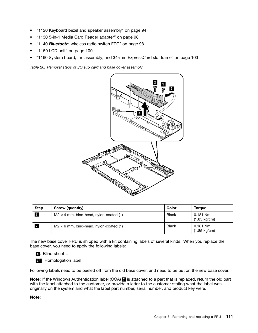
Table 26. Removal steps of I/O sub card and base cover assembly
| Step | Screw (quantity) | Color | Torque | |
|
|
|
|
|
|
|
|
| M2 × 4 mm, | Black | 0.181 Nm |
| 1 |
| |||
|
|
|
|
| (1.85 kgfcm) |
|
|
|
|
|
|
|
|
| M2 × 6 mm, | Black | 0.181 Nm |
| 2 |
| |||
|
|
|
|
| (1.85 kgfcm) |
|
|
|
|
|
|
The new base cover FRU is shipped with a kit containing labels of several kinds. When you replace the base cover, you need to apply the following labels:
8 : Blind sheet L
14 : Homologation label
Following labels need to be peeled off from the old base cover, and need to be put on the new base cover.
Note: If the Windows Authentication label (COA) 7 is attached to a part that is replaced, return the old part with the label attached to the customer, or provide a letter to the customer stating what the label was originally on the system and what the label part number, serial number, and product key were.
Note:
Chapter 8. Removing and replacing a FRU 111