NB Reference Thermal Solution #1
the thermal resistance of the Chomerics THERMFLOW T710 TIM is shown in Table
Table
Pressure (psi) | Thermal Resistance (°C × in2)/W |
5 | 0.37 |
|
|
10 | 0.30 |
|
|
20 | 0.21 |
|
|
30 | 0.17 |
|
|
NOTE:
1.All measured at 50°C.
6.5.5Heatsink Retaining Fastener
The reference solution uses four heatsink retaining Tufloks. The fasteners attach the heatsink to the motherboard by expanding its Tuflok prong to snap into each of the four heatsink mounting holes. These fasteners are intended to be used on a 0.062” thickness motherboard with either of the two NB reference thermal solutions. See Appendix B for a mechanical drawing of the fastener.
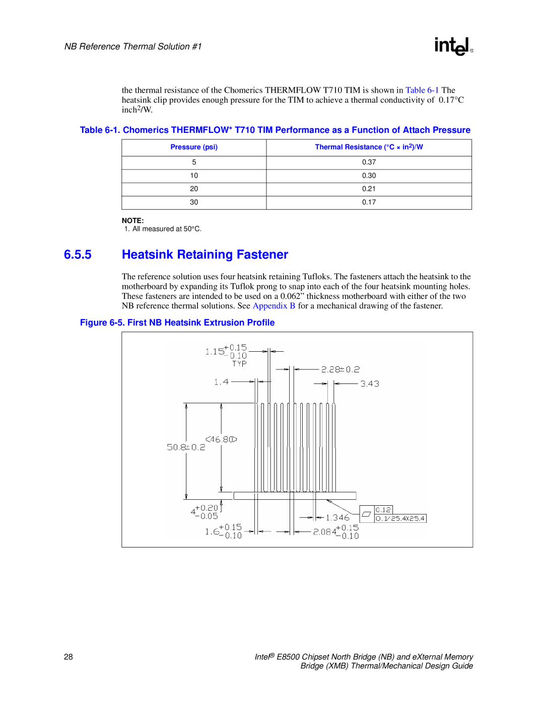
Figure 6-5. First NB Heatsink Extrusion Profile
28 | Intel® E8500 Chipset North Bridge (NB) and eXternal Memory |
| Bridge (XMB) Thermal/Mechanical Design Guide |