XMB Reference Thermal Solution
8.3Mechanical Design Envelope
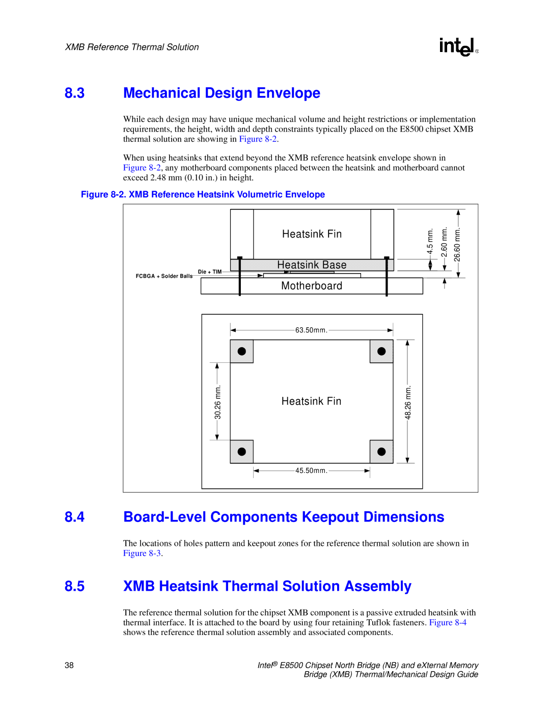
While each design may have unique mechanical volume and height restrictions or implementation requirements, the height, width and depth constraints typically placed on the E8500 chipset XMB thermal solution are showing in Figure
When using heatsinks that extend beyond the XMB reference heatsink envelope shown in Figure
Figure 8-2. XMB Reference Heatsink Volumetric Envelope
|
| Heatsink Fin | 4.5 mm. | 2.60 mm. | 26.60 mm. |
|
| Heatsink Base | |||
| Die + TIM |
|
|
| |
FCBGA + Solder Balls | Motherboard |
|
|
| |
|
|
|
|
| |
|
| 63.50mm. |
|
|
|
| mm. | Heatsink Fin | mm. |
|
|
| 30.26 | 48.26 |
|
| |
|
|
|
| ||
|
| 45.50mm. |
|
|
|
8.4Board-Level Components Keepout Dimensions
The locations of holes pattern and keepout zones for the reference thermal solution are shown in Figure
8.5XMB Heatsink Thermal Solution Assembly
The reference thermal solution for the chipset XMB component is a passive extruded heatsink with thermal interface. It is attached to the board by using four retaining Tuflok fasteners. Figure
38 | Intel® E8500 Chipset North Bridge (NB) and eXternal Memory |
| Bridge (XMB) Thermal/Mechanical Design Guide |