Packaging Technology
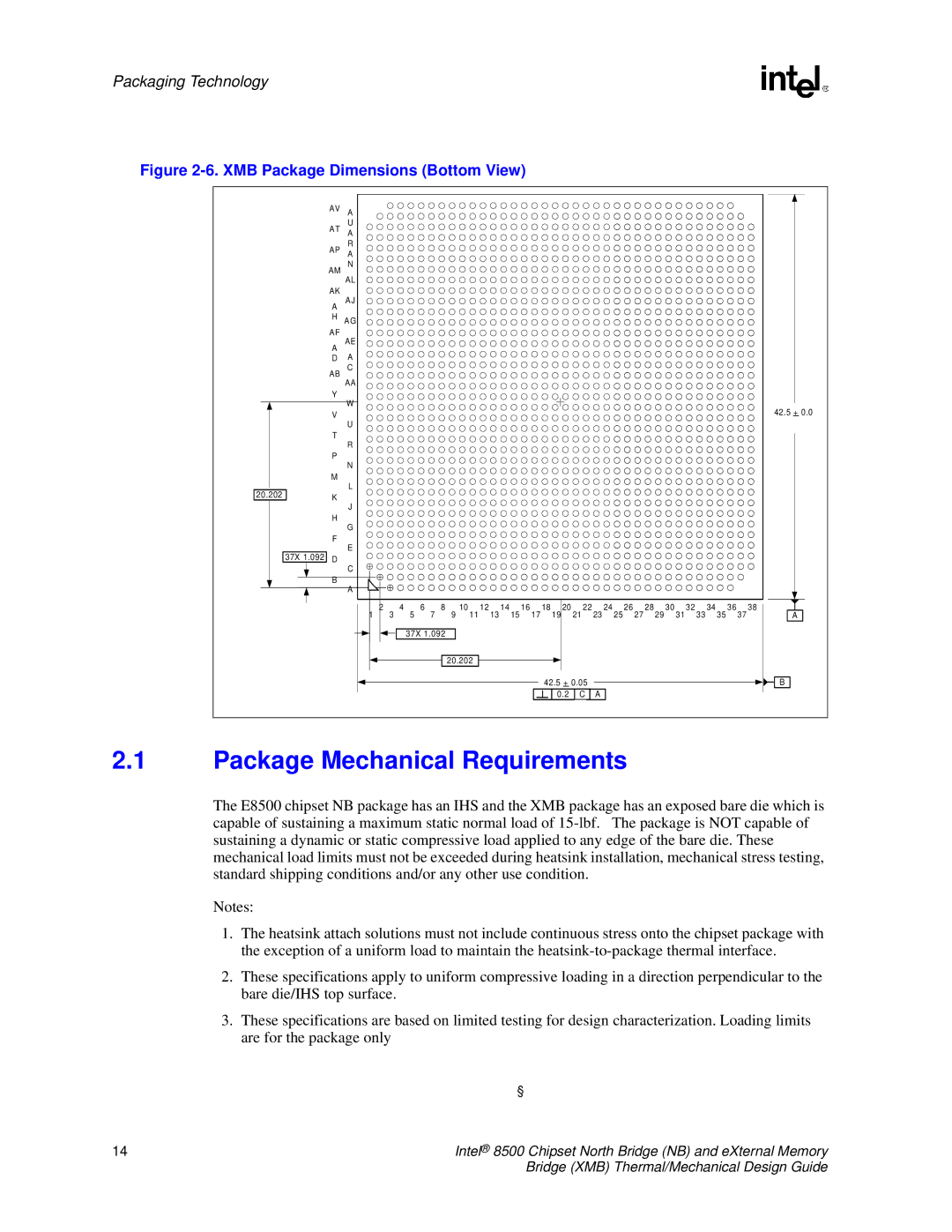
Figure 2-6. XMB Package Dimensions (Bottom View)
AV A
U
AT A
R
AP A
AM N
AL
AK
A AJ
H AG
AF
A AE
D A
AB C
AA
Y
W
V | 42.5 + 0.0 |
U
|
|
|
| T |
|
|
|
| R |
|
|
|
| P |
|
|
|
| N |
|
|
|
| M |
|
|
|
| L |
20.202 |
|
| K | |
|
|
|
| J |
|
|
|
| H |
|
|
|
| G |
|
|
|
| F |
|
|
|
| E |
|
|
|
| |
|
| 37X 1.092 | D | |
|
|
|
| C |
|
|
|
| |
|
|
|
| B |
|
|
|
| |
|
|
|
| A |
1 | 2 | 3 | 4 | 5 | 6 | 7 | 8 | 9 10 11 12 13 14 15 16 17 18 19 20 21 22 23 24 25 26 27 28 29 30 31 32 33 34 35 36 37 38 |
|
|
|
A | |||||||||||
37X 1.092
20.202
42.5 + 0.05 | B | |
0.2 | C | A |
2.1Package Mechanical Requirements
The E8500 chipset NB package has an IHS and the XMB package has an exposed bare die which is capable of sustaining a maximum static normal load of
Notes:
1.The heatsink attach solutions must not include continuous stress onto the chipset package with the exception of a uniform load to maintain the
2.These specifications apply to uniform compressive loading in a direction perpendicular to the bare die/IHS top surface.
3.These specifications are based on limited testing for design characterization. Loading limits are for the package only
| § |
14 | Intel® 8500 Chipset North Bridge (NB) and eXternal Memory |
| Bridge (XMB) Thermal/Mechanical Design Guide |