Manuals
/
Intel
/
Computer Equipment
/
Server
Intel
SE7500CW2
manual
Routing the Floppy Drive Cable
Models:
SE7500CW2
1
63
92
92
Download
92 pages
39.44 Kb
60
61
62
63
64
65
66
67
Install
Password
44 MB, 3 ½ default
Configuration Utilities
Solving Problems
Resetting the System
Using Bios Setup Utility
Keyboard Commands
Back Panel Connectors
Upgrading the Bios
Page 63
Image 63
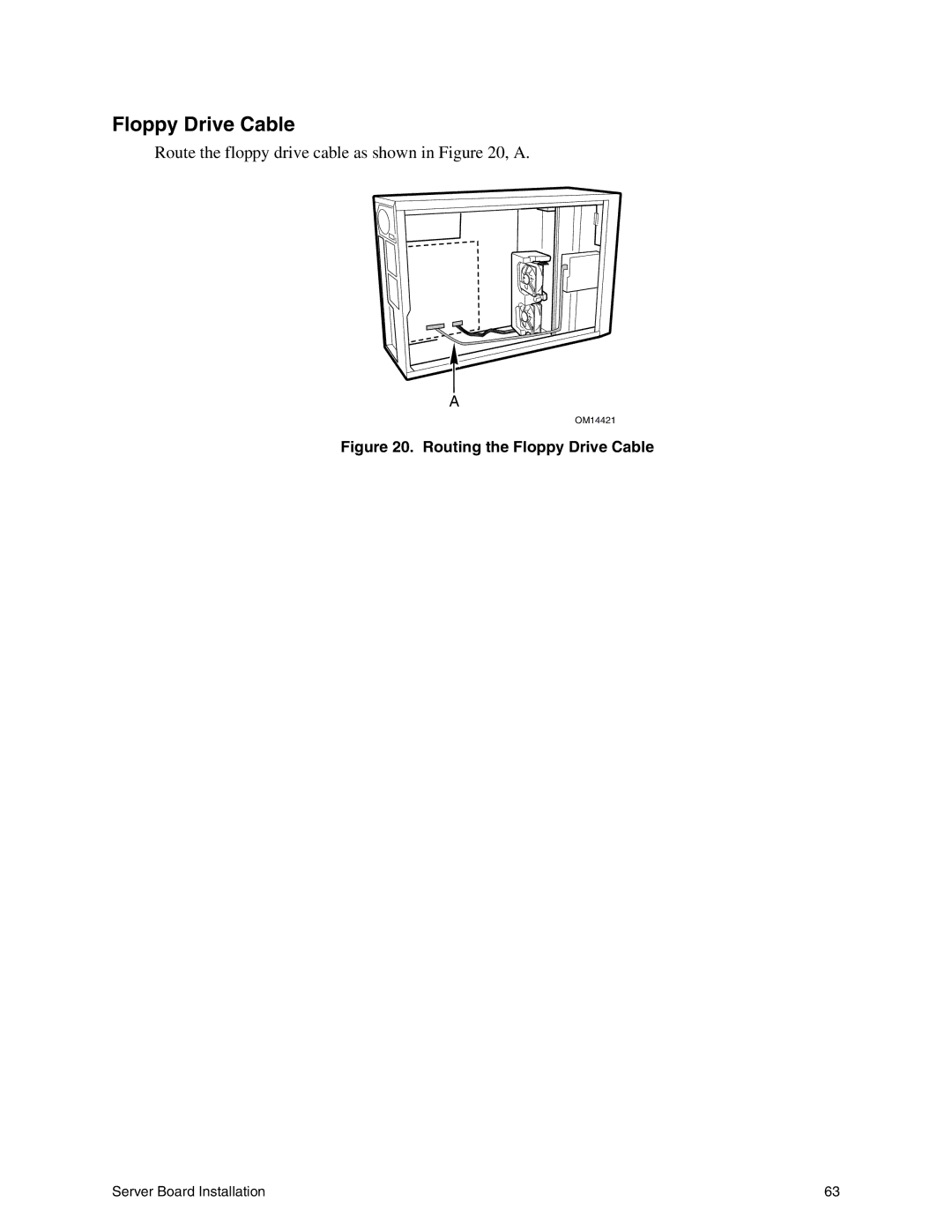
Floppy Drive Cable
Route the floppy drive cable as shown in
Figure 20,
A.
A
OM14421
Figure 20. Routing the Floppy Drive Cable
Server Board Installation
63
Page 62
Page 64
Page 63
Image 63
Page 62
Page 64
Contents
Intel Server Board SE7500CW2 Product Guide
Disclaimer
Contents
Upgrading
Solving Problems
Technical Reference
Regulatory and Integration Information
Index
Tables
Description
Server Board Features
Server Board Features
Feature
System I/O Power Security Form Factor
Back Panel Connectors
Back Panel Connectors
Server Board Connector and Component Locations
Server Board Connector and Component Locations
Processor
Dual Processor Operation
Boxed Processor Fan Heat sink
MCH
Intel E7500 Chipset
Parallel Port
Keyboard and Mouse Connectors
Super I/O
Serial Ports
PCI I/O Subsystem
Memory
Bit / 100 MHz PCI-X Capable Subsystem
Bit / 133 MHz PCI-X Capable Subsystem
Video Controller
Network Interface Controller NIC
32-bit/33 MHz PCI Subsystem
Wake on LAN
AC Link Mode
Password Protection
Security
Security Operation Summary
Using Passwords
Password Clear Jumper
Intel Server Board SE7500CW2 Product Guide
Description and brief procedure
Configuration Software and Utilities
Power-On Self-Test Post
Configuration Utilities
Setup Menus
Using Bios Setup Utility
If You Cannot Access Setup
Starting Setup
Press
Keyboard Commands
Menu Selection Bar Main Advanced Security
Power Boot System
Menu Selection Bar
On-Screen Options
Choices
44 MB, 3 ½ default
Main Menu
Main Menu
Primary/Secondary, Master/Slave Submenu
Disabled default
Enabled default Description
Primary/Secondary, Master/Slave Submenus
Win2000/.NET Default
Advanced Menu
Advanced Menu
Enabled default
Disabled default No default
DOS default
Auto Detect default
O Device Configuration Submenu
Device Configuration Submenu
ECP default Default
IRQ7 default
DMA 3 default
On Board Device Submenu
On Board Device Submenu
PCI Configuration Submenu
PCI Configuration Submenu
Option ROM Scan Submenu
Choices Enabled default
Choices Disabled default
Server Menu Submenu
Console Redirection Submenu
Console Redirection Submenu
Enabled default No default
Event Logging Submenu
Event Logging Submenu
Hardware Monitor Submenu
Hardware Monitor Submenu
Security Menu
If no password entered previously Feature
Enabled default User default
Security Menu
Last State default
Power Menu
Boot Menu
Power Menu
Boot Menu
Boot Priority
Device
Feature Choices
System Menu
System Menu
Port On Board Connector Designator
Exit Menu
Exit Menu
Obtaining the Upgrade Utility
Upgrading the Bios
Preparing for the Upgrade
Recording the Current Bios Settings
Upgrading the Bios
Recovering the Bios
Creating the Bios Upgrade Diskette
Changing the Bios Language
Hardware Monitoring
Monitored Headers and Sensors
Sensor Type
Intel Server Board SE7500CW2 Product Guide
Before You Begin
Server Board Installation
Safety Cautions
Tools and Supplies Needed
Safety and Regulatory Compliance
Processor
Installation Notes
Power Supply
Minimum Hardware Requirements
Installation Procedures
Installing the I/O Gasket and Shield
Attaching the Gasket to the I/O Shield
Attaching the Label to the I/O Shield
Installing the I/O Shield
Configuring Chassis Standoffs
Configuring Chassis Standoffs
Installing Rubber Bumpers
Installing Rubber Bumpers
Installing the Server Board
Placing the Server Board into the Chassis
Attaching the Server Board
Installing Memory
Installing Memory
Installing the Retention Brackets
Installing the Processors
Applying Thermal Grease
Attaching the Processor
Installing the Processor Wind Tunnel
Attaching the Processor Wind Tunnel Assembly
Attaching the Heat Sink
Attaching Intake and Exhaust Assemblies
Attaching the Heat Sink Fan
Installing the Optional Scsi Add-in Card
Making Connections to the Server Board
Making Connections to the Server Board
IDE Cables
Cable Routing
Routing the Floppy Drive Cable
Floppy Drive Cable
Making Back Panel Connections
Finishing Up
Upgrading
Memory
Installing DIMMs
Processors
Adding or Replacing a Processor
Attaching the Processor
Installing the Processor Wind Tunnel
OM14477
Removing a Processor
Replacing the Backup Battery
Varning
Intel Server Board SE7500CW2 Product Guide
Initial System Startup
Solving Problems
Resetting the System
Checklist
After the System Has Been Running Correctly
Running New Application Software
More Problem Solving Procedures
Preparing the System for Diagnostic Testing
Monitoring Post
Confirming Loading of the Operating System
Specific Problems and Corrective Actions
Power Light Does Not Light
Verifying Proper Operation of Key System Lights
Characters Are Distorted or Incorrect
No Characters Appear on Screen
Diskette Drive Activity Light Does Not Light
System Cooling Fans Do Not Rotate Properly
Cannot Connect to a Server
Problems with Network
Hard Disk Drive Activity Light Does Not Light
CD-ROM Drive Activity Light Does Not Light
Problems with Application Software
Bootable CD-ROM Is Not Detected
PCI Installation Tips
World Wide Web Telephone
Getting Help
Intel Server Board SE7500CW2 Product Guide
Jumper Name
Configuration Jumpers
Pins What happens at system reset
Technical Reference
Location
Pins Description
Front Panel Header
Front Panel Header Connection Descriptions
Product EMC Compliance
Product Safety Compliance
Regulatory and Integration Information
Product Regulatory Compliance
Electromagnetic Compatibility Notices
Product Regulatory Compliance Markings
Product Certification Markings
Taiwan Declaration of Conformity
Europe CE Declaration of Conformity
Australia / New Zealand
Korean RRL Compliance
ESD
Index
PCI
Top
Page
Image
Contents