CONTRACTURE FOOTPLATE OPTION | PROCEDURE 11 | |
|
|
|
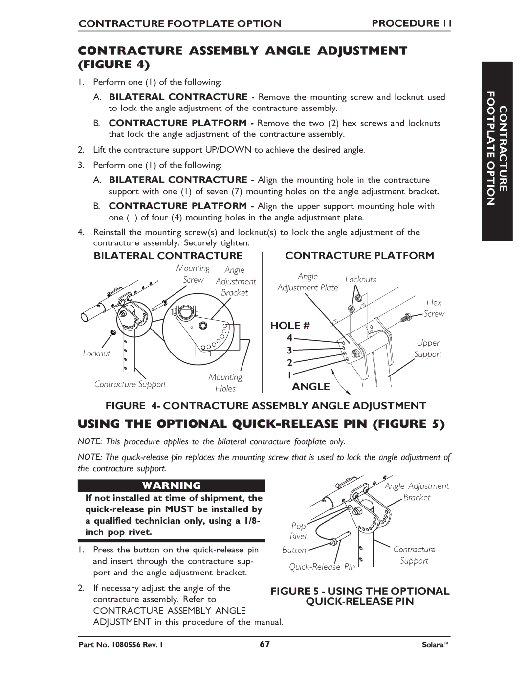
CONTRACTURE ASSEMBLY ANGLE ADJUSTMENT (FIGURE 4)
1.Perform one (1) of the following:
A.BILATERAL CONTRACTURE - Remove the mounting screw and locknut used to lock the angle adjustment of the contracture assembly.
B.CONTRACTURE PLATFORM - Remove the two (2) hex screws and locknuts that lock the angle adjustment of the contracture assembly.
2.Lift the contracture support UP/DOWN to achieve the desired angle.
3.Perform one (1) of the following:
A.BILATERAL CONTRACTURE - Align the mounting hole in the contracture support with one (1) of seven (7) mounting holes on the angle adjustment bracket.
B.CONTRACTURE PLATFORM - Align the upper support mounting hole with one (1) of four (4) mounting holes in the angle adjustment plate.
4.Reinstall the mounting screw(s) and locknut(s) to lock the angle adjustment of the contracture assembly. Securely tighten.
BILATERAL CONTRACTURE | CONTRACTURE PLATFORM | |||
| Mounting | Angle | Angle | Locknuts |
| Screw | Adjustment | ||
| Adjustment Plate | |||
|
| Bracket |
| |
|
|
| Hex | |
|
|
|
| |
|
|
| HOLE # | Screw |
|
|
|
| |
|
|
| 4 | Upper |
Locknut |
|
| 3 | |
|
| Support | ||
|
| 2 | ||
|
|
|
| |
Contracture Support | Mounting | 1 |
| |
| Holes | ANGLE |
| |
FIGURE 4- CONTRACTURE ASSEMBLY ANGLE ADJUSTMENT
USING THE OPTIONAL QUICK-RELEASE PIN (FIGURE 5)
NOTE: This procedure applies to the bilateral contracture footplate only.
NOTE: The
CONTRACTURE FOOTPLATE OPTION
WARNING
If not installed at time of shipment, the
1.Press the button on the
Angle Adjustment
Bracket
Pop
Rivet
Button | Contracture |
Support | |
|
2. If necessary adjust the angle of the | FIGURE 5 - USING THE OPTIONAL |
contracture assembly. Refer to | |
CONTRACTURE ASSEMBLY ANGLE |
|
ADJUSTMENT in this procedure of the manual.
Part No. 1080556 Rev. I | 67 | Solara™ |