MWD/FWD
R N I N G
E C I a L T E S
Wheelchair TIE-DOWN Restraints and Seat Positioning Straps
Table of Contents
Specification S
Specifications
High Back not available on model R2250 Series
LowandHighBackTypeshaveanInfiniteadjustment
Specifications
Are approximate
Procedure 1 of this manual
Inches
16 to 20-inches In 1-inch increments
Controller Settings for R2JR
General Guidelines Procedure
Repair or Service Information
Operating Information
Wiring Harness for Battery Box Lid
Procedure General Guidelines
Back View
General Guidelinesprocedure
Wiring Harness
Back View Motor Assembly Battery
For Battery
Side Frame
Not remove this label 1095559
Battery Warning Label Location
Procedure Troubleshooting
Using Hydrometer to Check Battery Cells Lead Acid Figure
Battery Charger Connector Digital Voltmeter
Field Load Test Figure
Motor Testing Figure
Troubleshooting Procedure
Number of Floating Balls
CapMotor
Pin Motor Connector Ohmmeter
Front Riggings Procedure
Adjusting FLIP-UP Removable Footboard
O N T I N G S
Angle Figure
Procedure Front Riggings
Adjusting the Removable Footboard
Adjusting Footboard Angle Figure
Depth Figure
Reinstall the caplug caps
Battery Tray
Front Hex ScrewFootboard Pivot Caplug Assemblies Washer
Perform one 1 of the following
Replacing Armrest Pads Figure
Procedure Arms
Replacing Armrest Plate Figure
M S
Replacing Seat Positioning Strap
SEAT/BACK Procedure
Replacing Back Upholstery Figure
A T C K
Replacing Captains Seat Figure
Assembly Washers Hex Screws Apply Loctite
Adjusting Back Height Figure
Adjusting Seat Depth Figure
Seat Frame Procedure
A T M E
Replacing Back Canes Figure
Changing Back Angle Figure
Detail B
Top Half of Back Canes
Bottom Half of Back Canes
A T
Hole
Wheelchair
Procedure Electronics
REMOVING/INSTALLING Mkiv Controller
Repositioning Mkiv Joystick
E C T R O N I C S
Mounting Stud on Wheelchair Frame
Electronics Procedure
Controller Washer
Inch Wide Models Figure
Tie-Wrap Battery Wiring Harness
Wire Connector Support
Mounting Stud on Wheelchair Frame Washer
Controller Locknuts
Limit Switch
Limit Switch Phono Plug
Limit Switch
Body
Procedure Limit Switch
Recline Angle 4 inches
Actuator 5o Seat Angle
Wheels Procedure
REMOVING/INSTALLING Drive Wheels
Replacing Pneumatic TIRES/ Tubes Drive WHEELS/CASTERS
Inch Drive Wheel Figure
Procedure Wheels
REMOVING/INSTALLING Drive Wheel HUB Figure
Installing
Removing
Locking
Keystock
Replacing Forks Figure
Replacing Casters Figure
ForkLocknut Hex Screw Washer WasherCaster
Dust Cover Locknut
Installing Side Shrouds
Weight Shift Basic Tilt Models Pro- ceed to Step
R O U D S
Position the side shroud on the wheelchair frame
Weight Shift Tilt Models Proceed to Step
Procedure Shrouds
Wheelchairs not Equipped with Weight Shift Basic Tilt
O U D S
Shrouds Procedure
Detail a
R O U
Crossbraces
Adjusting Seat Width Integrated Sling Seats Figure
O S S B R a C E S
FWD Wheelchairs
O S
Procedure Crossbraces
R a C E S
Pivot Link Locknut Steps 4
Replacing Crossbraces Captains Seats Figure
Steps 8
Dust Cover Steps 6
Tie Wraps Steps 7 Detail a Steps 9
Front Wheelchair
T T E R I E S
Batteries
Dual U1 or Dual Group 22 Battery Boxes
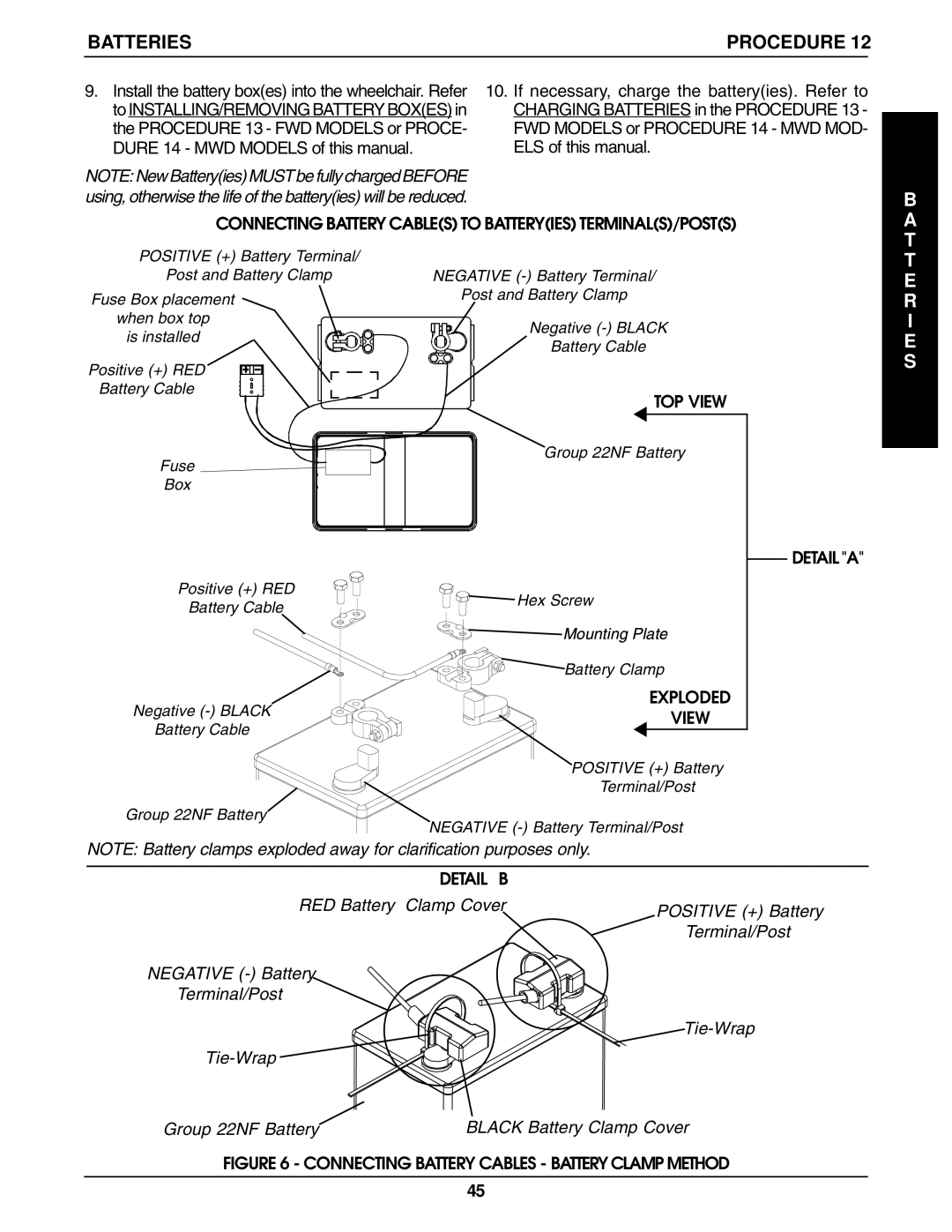
Connecting Battery Cables
Battery Cable
Direct Mount Method
Battery Orange Battery Terminal Cap
Positive + Battery Terminal/Post
+ Battery
Post Tie Wrap Group 22 NF Black BatteryTerminal BatteryCap
Battery Clamp Method Figures 4, 5
Installing Battery Clamp Covers
Battery Clamp Battery Cable
RED Battery Clamp Cover Positive + Battery
T E R I E S
Exploded
A I R S
Assembling Ranger II FWD
Integrated Sling Seats Figure
Unfolding the Wheelchair
Unfolding/Folding Captains Seat Figure
FWD Wheelchairs
Unfolding
Push Brackets Crossbraces
Description and Use of Battery Chargers
When to Charge Batteries Figure
Charging Batteries Figure
MCC-MKIV X, a or A+ Joystick
Cleaning Battery Terminals
Recommended Battery Types
Replacing Batteries
Required Items
R2BASIC and R2STANDARD Figure
INSTALLING/REMOVING Battery Boxes
Detaila
R2JR Figure
Battery Tray
Folding Battery Tray for Transport Figure
Unfolding Battery Tray for Use Figure
C H a I R S
Removing/Installing Battery Tray for R2BASIC
Changing Width of Battery Tray Figure
Installing Figure
Removing/Installing Battery Tray R2JR. Figure
For Model R2JR Figure
Replacing Left Battery Tray Hanger Bracket
Hanger Bracket for Model R2JR
For Models R2BASIC and R2STANDARD Figure
E E L C H a I R S
Replacing Wiring Harness Figure
Controller Locknut
Rear Locknut Loosen Screw But Do Not Remove
Phono Jack Nut Side Shroud Phillips Screws
Wiring Harness Tie Wraps
Spacers
Charger Cable Mounting Bracket
Inch Wide Models Figure
Replacing Wiring Harness 14-INCH Wide Models
Wire Connector Support Slot Phillips Screws
Users Weight 200 LBS and Under Motor Mounting Positions
Users Weight 201 to 250 LBS Motor Mounting Positions
Repositioning Motors Figure
R2 Basic and R2JR
Steps 6
Steps 2, 4, 10, 11
Motor Gearbox
Front Motor Mounting Position Middle Motor Rear Motor
Tip Steps 2, 6
Rotate battery tray hanger bracket up
Pin Steps 3
Clutch Handle Step
For R2JR only
Replacing MOTOR/GEARBOX R2STANDARD Figure
Steps 2
Battery Motor Connectors
Dust Cover Not Shown
13,14,15
Assembling Ranger II MWD
Unfolding/Folding Integrated Sling Seats Figure
Seat Rails Seat Guides
Unfolding/Folding Captains Seats Figure
MWD Wheelchairs
Indicator BDI
Battery Discharge
Shutoff Procedure
Mkiv X, a or A+ Joystick MKIV- RII Joystick
From Battery Charger Connector at
Battery Charger Connector on Side of Wheelchair
Battery Charger Three Pronged Plug Front View
Charger Port Joystick Battery Boxes
INSTALLING/REMOVING Battery Boxes Figure
Clean the new battery terminals
To remove the removable footboard, refer to Remov
Battery Tray Figure
Retaining Front Battery Box Strap Rear Strap Clip
Leads
Hanger Bracket Mounting
Slots Battery Tray
Battery Tray Pins Hex Bolts
Wiring
Procedure MWD Wheelchairs
E L C H a I R S
Cable Mounting Bracket may Vary depending on wheel
Stabilizer Identification Figure
Stabilizer Adjustment Nut Measure This Height
Type a Type B Type C
Spring
Terclockwise
Adjusting Stabilizer for User Preference
Hex Bolt Stabilizer Plates Cylinder
Hex Bolt Bottom of Stabilizer Cylinder
Stabilizer Locknut Lower Spring
Replacing Stabilizer Cylinders
Wheelchair Frame Jam Nut Locknuts TOP Hex Bolt
Stabilizer Plates
Type C Stabilizer Assemblies
Replacing Stabilizer Wheel
Hex Bolt Spacers Stabilizer Wheel
Replacing Stabilizer Cylinder Springs Figure
COUNTER-CLOCKWISE
16-20x Locknut
Replacing Clutch Handles R2BASIC and R2250 Series Figure
Repositioning Motors
Wheelchair Frame Short Socket
Tie Wrap Steps Battery Tray Mounting Bracket Motor Gearbox
Pin
Pin Step
Replacing MOTOR/GEARBOX R2STANDARD Figure
Dust Cover Motor/Gearbox
Battery Motor Connectors Steps 4 Steps 5, 6 Locknut
Page
R R a N T Y
Warranty
Chedworth Way