4. Piping
Discharge and suction piping should be no smaller than the respective pump opening and should be kept as short as possible, avoiding unnecessary fit- tings to minimize friction losses.
NOTICE: PIPING MUST BE INDEPENDENTLY SUP- PORTED AND NOT PLACE ANY PIPING LOADS ON THE PUMP.
If suction piping larger than pump suction is re- quired, an eccentric pipe reducer, WITH THE STRAIGHT SIDE UP, must be installed at the pump suction.
If the pump is installed below the liquid source, install a full flow isolation valve in the suction piping for pump inspection or maintenance.
NOTICE: DO NOT USE THE ISOLATION VALVE ON THE SUCTION SIDE OF THE PUMP TO THROTTLE PUMP. THIS MAY CAUSE LOSS OF PRIME, EXCESSIVE TEMPERA- TURES, DAMAGE TO PUMP AND VOID WARRANTY.
If pump is installed above the liquid source, the fol- lowing MUST be provided:
To avoid air pockets, no part of the suction pip- ing should be above the pump suction.
On any horizontal piping sections, slope piping upward from liquid source.
All suction pipe joints MUST be airtight.
Use a foot valve for priming, or for holding prime during intermittent duty.
The suction strainer or suction bell MUST be at least 3 times the suction pipe diameter.
Insure that the size and minimum liquid submer- gence, over the suction inlet, is sufficient to prevent air from entering through a suction vortex. See typi- cal suction piping Figures 1 through 4.
Install a discharge check valve, suitable to handle the flow and liquids, to prevent backflow.
Install an appropriately sized gate valve, AFTER the discharge valve, to regulate the pump capacity, for pump inspection and for maintenance.
When a pipe increaser is required, install between the check valve and the pump discharge.
|
| H min. |
| H min. |
|
|
|
|
|
| |
|
| D |
|
| D |
Figure 1 |
| H | Figure 2 | ||
|
| feet | 16 |
|
|
|
| 15 |
|
| |
|
| in | 14 |
|
|
|
| 13 |
|
| |
|
| Submergence |
|
| |
|
| 6 |
|
| |
|
|
| 12 |
|
|
D |
|
| 11 |
|
|
|
| 10 |
|
| |
|
|
| 9 |
|
|
| 8D |
| 8 |
|
|
|
| 7 |
|
| |
| min. | Min.= | 5 |
|
|
| H min. |
|
| ||
| 2 |
|
| ||
4D |
|
| 4 |
|
|
|
| 3 |
|
| |
min. |
| H | 1 |
|
|
|
|
|
| ||
3D | 3D min. | 3D | 0 | 1 2 3 4 5 6 7 8 9 10 11 12 13 14 15 16 V | |
| 2 |
| V = Velocity in feet per second | ||
|
|
| |||
|
|
|
| = GPM x 0.321 | GPM x 0.4085 |
Figure 3 |
|
| Area | D2 | |
|
| Figure 4 | |||
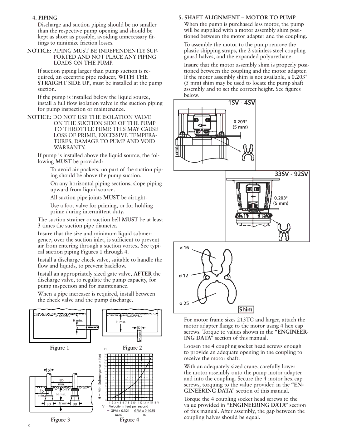
5.Shaft Alignment – Motor to Pump When the pump is purchased less motor, the pump will be supplied with a motor assembly shim posi- tioned between the motor adapter and the coupling.
To assemble the motor to the pump remove the plastic shipping straps, the 2 stainless steel coupling guard halves, and the expanded polyurethane.
Insure that the motor assembly shim is properly posi- tioned between the coupling and the motor adapter. If the motor assembly shim is not available, a 0.203" (5 mm) shim may be used to locate the pump shaft assembly and to set the correct height. See figures below.
0.203"
(5 mm)
0.203"
(5 mm)
Shim
For motor frame sizes 213TC and larger, attach the motor adapter flange to the motor using 4 hex cap screws. Torque to values shown in the “ENGINEER- ING DATA” section of this manual.
Loosen the 4 coupling socket head screws enough to provide an adequate opening in the coupling to receive the motor shaft.
With an adequately sized crane, carefully lower the motor assembly onto the pump motor adapter and into the coupling. Secure the 4 motor hex cap screws, torquing to the value provided in the “EN- GINEERING DATA” section of this manual.
Torque the 4 coupling socket head screws to the value provided in “ENGINEERING DATA” section of this manual. After assembly, the gap between the coupling halves should be equal.