adequately sized crane, carefully remove the mo- tor. DO NOT rest the motor on the motor shaft.
5.Remove the 4 tie rod nuts and lock washers.
6.Carefully remove the motor adapter by sliding it up the pump shaft. Larger units may require an adequately sized crane to lift the motor adapter. DO NOT damage the shaft.
NOTICE: EDGES OF THE STAINLESS STEEL PARTS ARE SHARP. WEAR APPROPRIATE PRO- TECTIVE CLOTHING.
7.To gain access to the mechanical seal, it is neces- sary to remove the stainless steel upper plate which is held in place by an
8.Remove the stationary element from the upper plate. With a clean cloth, wipe the upper plate bore clean and inspect for damage. Replace the
upper plate, as required. | A |
|
9.Remove the top (vented) stainless steel inner cas- ing. Grasp the pump shaft, below the mechanical seal, and move it sharply back and forth to free the first stage from the lower pump body. Remove the entire stack assembly from the pump external sleeve.
10.Slide the mechanical seal rotary element, spring and washer from the pump shaft. Discard the entire mechanical seal assembly.
11.Lubricate the inside of the new mechanical seal as- sembly with a quality grade of
12.To install a new mechanical seal rotary assembly, slide the assembly onto the pump shaft, spring end first. Be sure the top spring tip is in the hole of the rotary portion of the seal. DO NOT scratch or otherwise damage the seal face. With a clean, lint free cloth, wipe the seal face clean of all lubricant or debris.
13.Lubricate the outside of the new mechanical seal stationary element with a quality grade of
14.Insert the stationary seat into the seal housing with the seal face out. DO NOT scratch or other- wise damage the seal face. Insure that the station- ary seat is fully seated into the seal housing. With a clean, lint free cloth, wipe the seal face clean of all lubricant or debris.
15.With a new
16.Place the motor adapter over the 4 tie rod bolts, using an adequately sized crane when required, and install the 4 lock washers and tie rod nuts.
Torque the nuts, in sequence, to the value pro- vided in the “ENGINEERING DATA” section of this manual.
17.With an adequately sized crane, carefully lower the motor onto the motor adapter, lining up the electrical conduit connection and the 4 motor adapter bolt holes, as required.
18.Install the 4 motor hex cap screws, torquing to the value provided in the “ENGINEERING DATA” section of this manual.
19.Place the coupling drive pin into the pump shaft and install the coupling halves onto the motor and pump shafts. Install the 4 coupling socket head screws, lock washers and nuts, DO NOT tighten.
20.Position the motor assembly shim between the coupling and the motor adapter. If the motor assembly shim is not available, a 0.203" (5 mm) shim may be used to locate the pump shaft assem- bly and to set the correct height.
21.Tighten the 4 coupling socket head screws, torquing screws to values provided in the “ENGI- NEERING DATA” section of this manual. Tighten evenly so that the gap between the halves is equal side to side and top to bottom.
22.Install the 2 coupling guard halves.
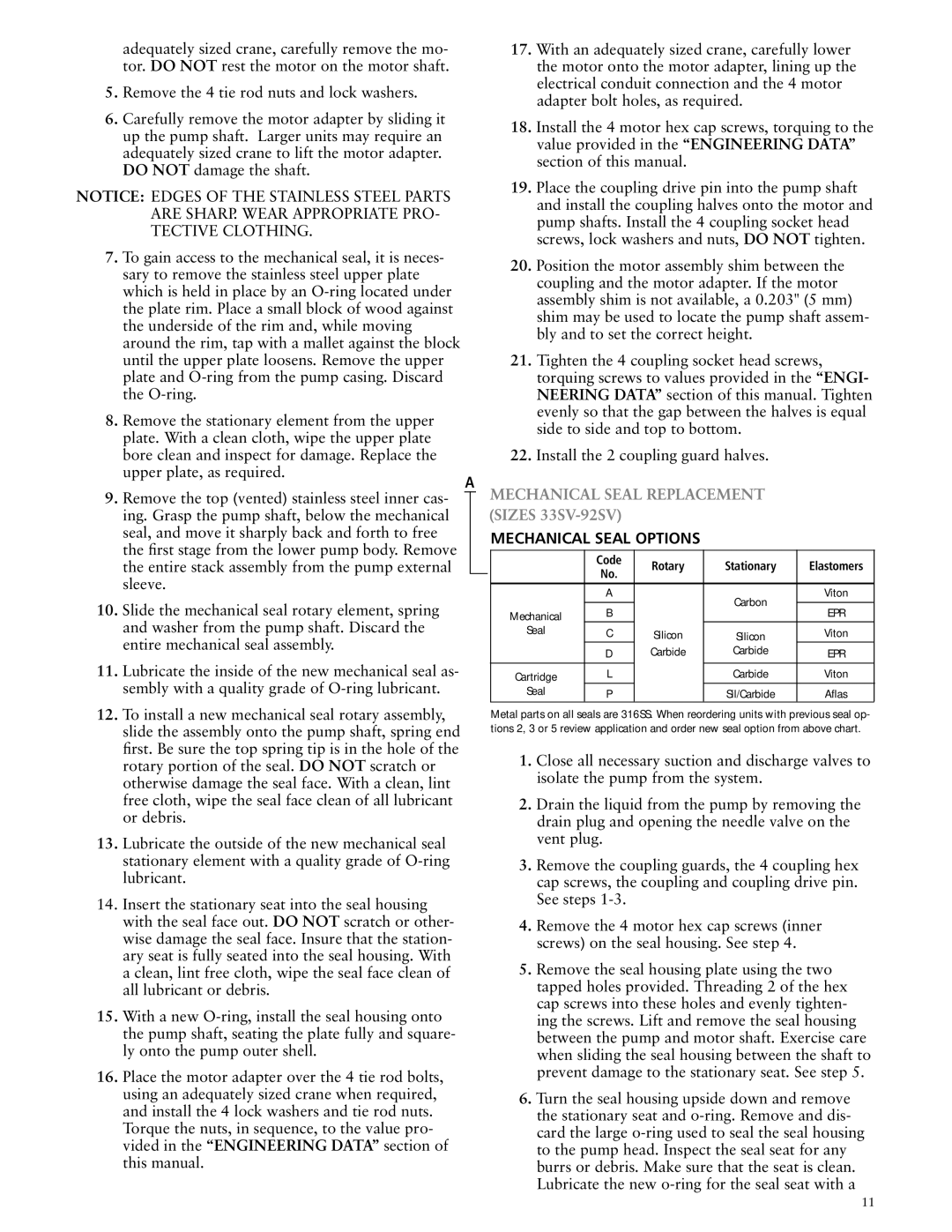
MECHANICAL SEAL OPTIONS
| Code | Rotary | Stationary | Elastomers |
| No. | |||
|
|
|
| |
| A |
| Carbon | Viton |
|
|
|
| |
Mechanical | B |
| EPR | |
|
| |||
Seal | C | Silicon | Silicon | Viton |
| D | Carbide | Carbide | EPR |
|
|
|
|
|
Cartridge | L |
| Carbide | Viton |
Seal | P |
| Sil/Carbide | Aflas |
Metal parts on all seals are 316SS. When reordering units with previous seal op- tions 2, 3 or 5 review application and order new seal option from above chart.
1.Close all necessary suction and discharge valves to isolate the pump from the system.
2.Drain the liquid from the pump by removing the drain plug and opening the needle valve on the vent plug.
3.Remove the coupling guards, the 4 coupling hex cap screws, the coupling and coupling drive pin. See steps
4.Remove the 4 motor hex cap screws (inner screws) on the seal housing. See step 4.
5.Remove the seal housing plate using the two tapped holes provided. Threading 2 of the hex cap screws into these holes and evenly tighten- ing the screws. Lift and remove the seal housing between the pump and motor shaft. Exercise care when sliding the seal housing between the shaft to prevent damage to the stationary seat. See step 5.
6.Turn the seal housing upside down and remove the stationary seat and
11