Lift and handle the product carefully,
using suitable lifting equipment. Observe all the accident prevention regulations.
When you receive the pump, check the outside of the package for evident signs of damage. If the prod- uct bears visible signs of damage, notify our distribu- tor within 8 days from the delivery date.
2.Storing the Packed Product Ambient temperature 32º F to 104º F.
Short Term: (Less than 6 months) Goulds Pumps normal packaging procedure is designed to protect the pump during shipping. Upon receipt, store in a covered and dry location.
Long Term: (More than 6 months) Rotate shaft several times every 3 months. Refer to driver and coupling manufacturers for their long term storage procedures. Store in a covered dry location.
3. Unpacking the Product
Use suitable equipment. Observe all the accident prevention regulations in force. Lift and handle the product carefully, using suit- able lifting equipment.
When you receive the pump, check the outside of the package for evident signs of damage. If the prod- uct bears visible signs of damage, notify our distribu- tor within 8 days from the delivery date.
4. Handling the Product
Lift and handle the product carefully, using suitable lifting equipment. Observe the accident prevention regulations in force.
The product must be securely harnessed for lifting and handling. Some electric pumps have eyebolts that can be used for this purpose.
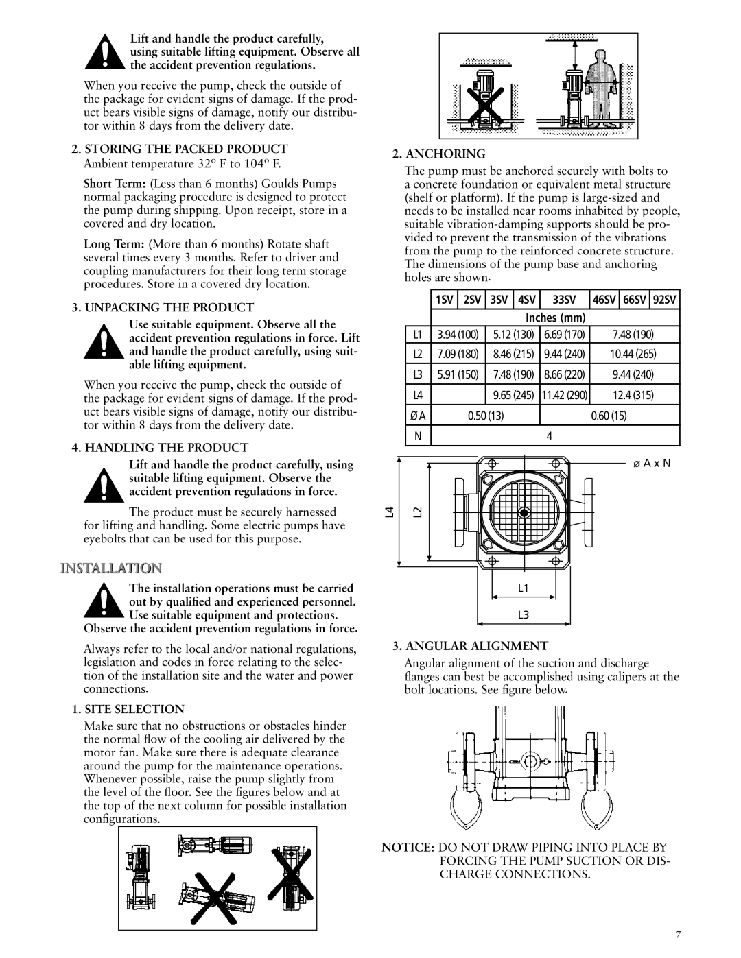
2. Anchoring
The pump must be anchored securely with bolts to a concrete foundation or equivalent metal structure (shelf or platform). If the pump is
| 1SV | 2SV | 3SV | 4SV | 33SV | 46SV | 66SV | 92SV |
|
|
|
|
|
|
|
|
|
|
|
|
| Inches (mm) |
|
|
| |
L1 | 3.94 (100) | 5.12 (130) | 6.69 (170) | 7.48 (190) | ||||
L2 | 7.09 (180) | 8.46 (215) | 9.44 (240) | 10.44 (265) | ||||
|
|
|
|
|
|
|
|
|
L3 | 5.91 (150) | 7.48 (190) | 8.66 (220) | 9.44 (240) | ||||
|
|
|
|
|
|
|
|
|
L4 |
|
| 9.65 (245) | 11.42 (290) | 12.4 (315) | |||
|
|
|
|
|
|
|
|
|
Ø A | 0.50 (13) |
|
| 0.60 (15) |
| |||
|
|
|
|
|
|
|
|
|
N |
|
|
|
| 4 |
|
|
|
|
|
|
|
|
|
|
|
|
ø A x N
L4 | L2 |
The installation operations must be carried out by qualified and experienced personnel. Use suitable equipment and protections.
Observe the accident prevention regulations in force.
Always refer to the local and/or national regulations, legislation and codes in force relating to the selec- tion of the installation site and the water and power connections.
1. Site Selection
Make sure that no obstructions or obstacles hinder the normal flow of the cooling air delivered by the motor fan. Make sure there is adequate clearance around the pump for the maintenance operations. Whenever possible, raise the pump slightly from the level of the floor. See the figures below and at the top of the next column for possible installation configurations.
L1
L3
3. Angular Alignment
Angular alignment of the suction and discharge flanges can best be accomplished using calipers at the bolt locations. See figure below.
NOTICE: DO NOT DRAW PIPING INTO PLACE BY FORCING THE PUMP SUCTION OR DIS- CHARGE CONNECTIONS.