For the 33 through 92SV sizes using a cartridge seal, after coupling bolts have been properly torqued, there are four set screws on the collar of the car- tridge seal that require tightening before removing the shim. The four hex head set screws require a 1/8" allen wrench and are to be tightened
Remove the motor assembly shim and retain for future use.
Install the 2 coupling guard halves.
1. Water Connection
The water connections must be made by qualified installation technicians in compliance with the regu- lations in force.
In case of connection to the water system, the regu- lations issued by the competent authorities (mu- nicipal, public utility company) must be observed. Authorities often require the installation of a back- flow prevention device, such as a disconnector, check valve or disconnection tank.
2. Wiring and Grounding
Single Phase Motors – Connect the BLACK wire to the BLACK motor wire. Connect the WHITE wire to the WHITE motor wire. Connect the GREEN wire to the GREEN motor wire.
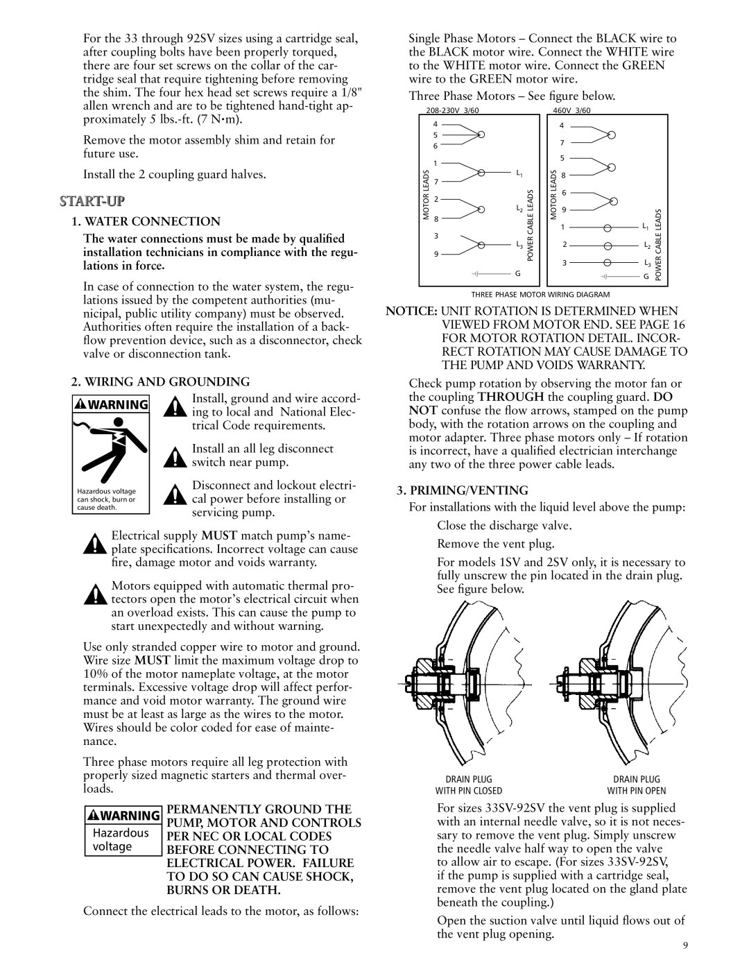
Three Phase Motors – See figure below.
|
| 460V 3/60 |
|
| |||
| 4 |
|
|
| 4 |
|
|
| 5 |
|
|
| 7 |
|
|
| 6 |
|
|
|
|
| |
|
|
|
|
|
|
| |
| 1 |
|
|
| 5 |
|
|
|
|
|
|
|
|
| |
LEADSMOTOR | 7 | L1 | LEADSCABLEPOWER | LEADSMOTOR | 8 | G | LEADSCABLEPOWER |
G |
| ||||||
|
|
|
|
|
|
| |
| 2 |
|
|
| 6 |
|
|
| L2 |
|
|
|
|
| |
|
|
|
| 9 |
|
| |
| 8 |
|
|
| 1 | L1 |
|
| 3 |
|
|
|
| ||
| L3 |
|
| 2 | L2 |
| |
| 9 |
|
|
| |||
|
|
|
| 3 | L3 |
| |
|
|
|
|
|
| ||
THREE PHASE MOTOR WIRING DIAGRAM
NOTICE: UNIT ROTATION IS DETERMINED WHEN VIEWED FROM MOTOR END. SEE PAGE 16 FOR MOTOR ROTATION DETAIL. INCOR- RECT ROTATION MAY CAUSE DAMAGE TO THE PUMP AND VOIDS WARRANTY.
Check pump rotation by observing the motor fan or
![]()
![]() WARNING
WARNING
Hazardous voltage can shock, burn or cause death.
Install, ground and wire accord- ing to local and National Elec- trical Code requirements.
Install an all leg disconnect switch near pump.
Disconnect and lockout electri- cal power before installing or servicing pump.
the coupling THROUGH the coupling guard. DO NOT confuse the flow arrows, stamped on the pump body, with the rotation arrows on the coupling and motor adapter. Three phase motors only – If rotation is incorrect, have a qualified electrician interchange any two of the three power cable leads.
3. Priming/Venting
For installations with the liquid level above the pump:
Electrical supply MUST match pump’s name- plate specifications. Incorrect voltage can cause fire, damage motor and voids warranty.
Motors equipped with automatic thermal pro- tectors open the motor’s electrical circuit when an overload exists. This can cause the pump to
start unexpectedly and without warning.
Use only stranded copper wire to motor and ground. Wire size MUST limit the maximum voltage drop to 10% of the motor nameplate voltage, at the motor terminals. Excessive voltage drop will affect perfor- mance and void motor warranty. The ground wire must be at least as large as the wires to the motor. Wires should be color coded for ease of mainte- nance.
Three phase motors require all leg protection with properly sized magnetic starters and thermal over- loads.
Close the discharge valve. Remove the vent plug.
For models 1SV and 2SV only, it is necessary to fully unscrew the pin located in the drain plug. See figure below.
DRAIN PLUG | DRAIN PLUG |
WITH PIN CLOSED | WITH PIN OPEN |
![]() WARNING
WARNING
Hazardous voltage
PERMANENTLY GROUND THE PUMP, MOTOR AND CONTROLS PER NEC OR LOCAL CODES BEFORE CONNECTING TO ELECTRICAL POWER. FAILURE TO DO SO CAN CAUSE SHOCK, BURNS OR DEATH.
For sizes
to allow air to escape. (For sizes
Connect the electrical leads to the motor, as follows:
Open the suction valve until liquid flows out of the vent plug opening.