ERX Hardware Guide
Series Routing Platforms ERX Hardware Guide, Release
End User License Agreement
Page
Table of Contents
Chapter Unpacking and Inspecting ERX Routers
Part Initial Installation
Chapter Cabling ERX Routers
Part
Procedures
Part Appendixes
Appendix a System Specifications
Part Index
Objectives
About This Guide
Audience
Convention Description Examples
Series Routers
Documentation Conventions
Icon Meaning Description
List of Technical Publications
Issue the clock source
Xiv
JUNOSe Software Guides
Xvi
Documentation Feedback
Obtaining Documentation
Requesting Support
Product Overview
Product Overview
Overview
ERX Overview
ERX Routers
ERX-14xx Models
ERX-14xx Models, Front View
ERX-14xx Models, Rear View
ERX-7xx Models
ERX-7xx Models, Front View
ERX-310 Router, Front View AC Model
ERX-310 Router
ERX-310 Router, Rear View AC Model
ERX Modules
Modules in ERX-14xx Models
SRP Module
SRP Module for ERX-7xx and ERX-14xx Models
Module Details
SRP I/O Module
SRP Module Redundancy
Line Modules
Representative Line Module
Modules
Network Management Tools
Redundancy Features
NVS Cards
Shows the data flow when a spare line module becomes active
Data Flow When a Spare Line Module Is Active
Power
Fans
Initial Installation
Initial Installation
Before You Begin
Unpacking and Inspecting ERX Routers
Unpacking ERX-14xx Models
Removing an L-Bracket
Unpacking ERX-7xx Models and ERX-310 Routers
Next Step
Inspecting Router Components and Accessories
If You Detect or Suspect Damage
Contacting Juniper Networks
ERX 8.0.x Hardware Guide Next Step
Freestanding Installation
Installing ERX Routers
Installation Guidelines
Rack-Mounted Installation
Installing ERX Routers
ERX Routers Installed in Recommended Order
Safety Guidelines
Installing ERX Routers Rack-Mounted Installation
Preparing the Equipment Racks
Installing the Router
Next Step
ERX 8.0.x Hardware Guide Next Step
Installing Modules
Orientation of Line Modules in ERX Routers
Slot Groups
Slot Groups for the ERX-7xx Models
GE-2 Line Modules
Managing Modules Using the Software
Combinations of Line Modules In Slot Groups
OC48 Line Modules
Grounding Jack Locations Series Router
Connecting the Wrist Strap to the ERX-310 Router Rear
Required Tools and Safety Items
Order of Installation
Safety Guidelines
SRP Module Slot Assignments Router
Installing SRP I/O and SRP Modules
Installing an SRP Module
Installing an SRP I/O Module
Ejectors in the Open Position
Installing a Line Module or an I/O Module
Installing Line and I/O Modules
Module Slot Assignments Router
Removing a Line Module, SRP Module, or SRP I/O Module
Ejectors in the Closed Position
Installing the Line Modules
Installing Components for Line Module Redundancy
Installing the Redundancy Midplane
Enter the halt command
Installing a Redundancy Midplane
Installing the I/O Modules
Configuring Line Module Redundancy
Verifying the Installation
ERX 8.0.x Hardware Guide Next Step
Cabling Overview
Cabling ERX Routers
ERX Ports and Connectors ERX-14xx Model Shown
Required Cables Connection Port and Cable Used
Required Tools, Wires, and Cables
External Timing Ports
Cabling the SRP I/O Module
SRP I/O Ports Description
Cabling ERX Routers
SRP I/O Module for ERX-14xx Models
SRP I/O Module for the ERX-310 Router
Management Ports
Cabling the Router for Power
Connecting to the Network
ERX-14xx models
Power Input Module Cables and Wires Needed Cable/Wire From
Power Input Module for ERX-14xx Models
Task 1 Turn Off All Router Power
Task 2 Connect the Grounding Cables
Task 3 Connect the Power Cables
ERX 8.0.x Hardware Guide
ERX-310 Router AC Model
Hssi Connectors
BNC Connectors
Cabling I/O Modules
RJ-48C Connectors
RJ-45 Connectors
SC Duplex Connectors
LC Duplex Connectors
Class 1 LED Product
O Module with SC Full Duplex Connectors
SMB Connectors
O Module with SMB Connectors
21/V.35 Connectors
Redundant Ports
21/V.35 Module with 50-Pin X.21/V.35 Connector
Before You Power Up the System
Powering Up ERX Routers
Powering Up
Initialization Sequence
Status LEDs
Powering Down
ERX 8.0.x Hardware Guide Next Step
Setting Up Management Access
Accessing ERX Routers
Using HyperTerminal
Console Port Setup
Connecting Directly to the Router
Management Ports for ERX Routers
Assigning an IP Address
Telnet Setup
Enter the configure command
Snmp
Maintaining ERX Routers on Troubleshooting on
Page
Required Tools and Items
Maintaining ERX Routers
Storing Modules and Components
Cleaning the System
Upgrading a System That Contains One SRP Module
Upgrading NVS Cards on SRP Modules
Upgrading a System That Contains Two SRP Modules
Replacing an NVS Card
NVS Card Slot on SRP Module
Upgrading Memory on SRP Modules
Removing SODIMMs
Displaying the Memory Installed
Sodimm Sockets on the SRP-5 and SRP-10 Module
Adding New SODIMMs
Replacing SFPs on I/O Modules
Verifying the Upgrade
Possible Release Mechanisms on the SFP
Removing SFPs
Example of SFP
Installing SFPs
Installing an SFP on a GE I/O Module
Replacing Fan Trays
Fan Tray in ERX-14xx Models
Removing the Fan Tray
Installing the Fan Tray
100
Installing a Cable-Management Bracket on ERX-7xx Models
101
102
Diagnosing Problems
Troubleshooting
Causes of Power Failures Symptom Possible Problems Actions
Troubleshooting Power Failures
Understanding Status LEDs to Troubleshoot
Redundant
LED Identification
106
107
SRP Module LEDs
109
LED Activity
Normal Activity of Functional Status Leds During Booting
Status Process
Issue the reload slot slotnumber
112
Redundancy Status
Monitoring Temperatures of Modules
Redundancy Status of a Line Module
Double-Bit Errors on SRP Modules
Resetting Line Modules and SRP Modules
Detecting Double-Bit Errors
Fixing Double-Bit Errors
116
Appendixes
Appendixes
ERX-14xx Models Specifications
System Specifications
ERX-14xx Models Specifications Category
Space Requirements
Category Specification
121
ERX-7xx Models Specifications Category
ERX-7xx Models Specifications
123
124
ERX-310 Router Specifications Category
ERX-310 Router Specifications
126
127
128
Your Preinstallation Responsibilities
Installation Guidelines Requirements
Regulatory Compliances
Environmental Requirements
Installation Guidelines and Requirements Safety Guidelines
ERX-310 Router Warnings AC Model
ERX-310 Power Cord Warnings AC Model
Equipment Rack Requirements
Mechanical Requirements
ERX Routers Installed in a Rack
Space Requirements
Proper Rack Installation
Airflow for ERX Routers
Cabling Recommendations
Product Reclamation and Recycling Program
Federal Communications Commission FCC Statement
Hardware Compliance
Industry Canada Notice CS-03
FCC Requirements for Consumer Products
Avis CS-03 d’Industrie Canada
C. Explanatory Notes Equipment Attachment Limitations
EC Declaration of Conformity
SRP I/O Module
Cable Pinouts
SRP I/O Module Serial Port
SRP I/O Module-RS-232 Serial Connector Pinout Signal
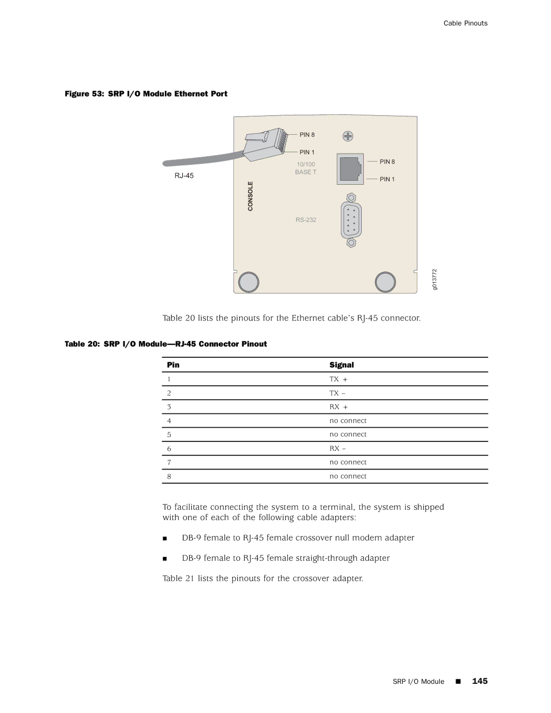
SRP I/O Module Ethernet Port
SRP I/O Module-RJ-45 Connector Pinout Signal
Lists the pinout for the straight-through adapter
CT1 and CE1 I/O Modules
CT1 I/O Module Ports
CT1/CE1 I/O Module-RJ-48C Connector Pinout Signal
Pinout of 50-Pin Telco Connector to Ports Signal
CE1 I/O Module with Telco Connectors
149
Pin Signal
150
Contacting Customer Support and Returning Hardware
Return Procedure
Contacting Customer Support
152
Locating Component Serial Numbers
Representative Module Serial Number ID Label
Information You Might Need to Supply to Jtac
Tools and Parts Required
Returning Products for Repair or Replacement
Packing Instructions for Returning a Chassis
155
156
Declaration of Conformity
Declaration of Conformity
158
Index
Index
Accessing
Symbols
Series routers
Modules
QoS, packet classification for
21/V.35 connectors, cabling