NAMES AND FUNCTIONS OF PARTS
– Front panel – (continued)
|
|
|
|
|
|
|
| OPERATE |
|
Mini | MENU | DISP | RESET | PROFESSIONAL | A.DUB |
| REC | PLAY | PAUSE |
|
|
|
|
|
|
|
|
| |
| SEARCH– | SET | SEARCH+ |
|
|
|
|
|
|
|
|
|
|
| EJECT |
| REW | STOP | FF |
MIC | HOLD | BLANK | CUE UP |
|
|
|
|
|
|
|
|
|
|
|
|
| |||
| PHONES | REC LEVEL |
|
|
| AUDIO | INPUT | REMOTE | |
|
|
|
|
| COUNTER MONITOR OUTPUT SELECT | ||||
|
|
|
|
| CTL | L | DV |
| |
|
|
|
|
| TC | MIX | MIX | LINE |
|
|
|
| UB | R | Y/C | LOCAL | |||
|
|
|
|
|
|
|
| (CPN) | |
| 9 | 8 7 6 5 4 |
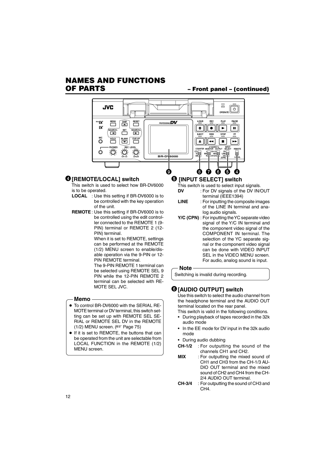
4[REMOTE/LOCAL] switch | 5 [INPUT SELECT] switch | |
This switch is used to select how
LOCAL : Use this setting if
REMOTE : Use this setting if
When it is set to REMOTE, settings can be performed at the REMOTE (1/2) MENU screen to enable/dis- able operation via the
The
MOTE SEL JVC.
This switch is used to select input signals.
DV : For DV signals of the DV IN/OUT terminal (IEEE1394)
LINE : For inputting the composite images of the LINE IN terminal and ana- log audio signals.
Y/C (CPN) : For inputting the YC separate video signal of the Y/C IN terminal and the component video signal of the COMPONENT IN terminal. The selection of the YC separate sig- nal or the component video signal can be done with VIDEO INPUT SEL in the VIDEO MENU screen. For audio, analog sound is input.
Note
Switching is invalid during recording.
6[AUDIO OUTPUT] switch
Memo
●To control
RIAL or REMOTE SEL DV in the REMOTE (1/2) MENU screen. (☞ Page 75)
●If it is set to REMOTE, the buttons that can be operated from the unit are selectable from LOCAL FUNCTION in the REMOTE (1/2) MENU screen.
Use this switch to select the audio channel from the headphone terminal and the AUDIO OUT terminal located on the rear panel.
This switch is valid in the following conditions.
•During playback of tapes recorded in the 32k audio mode
•In the EE mode for DV input in the 32k audio mode
•During audio dubbing
MIX : For outputting the mixed sound of CH1 and CH3 from the
12