8[SYNC IN] synchronization input
terminal (BNC)
This is the terminal for inputting reference syn- chronization signals from an external source. For external synchronization signals, input com- posite video signals of 1V
(☞ Page 29 “Synchronization signal”)
9[TIME CODE IN] terminal (BNC)
This is the
It is for connecting to an external time code gen- erator.
For external time code signals, use those that synchronize with the video signals.
•To input external time codes, set TCG SOURCE of the TC/UB/CLOCK Menu to “EX- TERNAL”.
0[TIME CODE OUT] terminal (BNC)
This is the
It outputs time codes recorded on the tape dur- ing playback and data generated by the time code generator during recording.
With the COUNTER switch set to CTL, time code is not output.
![CH1/3 AUDIO IN] terminal (RCA)
Use this terminal to input analog audio signals. To enable audio input via this terminal, set the INPUT SELECT switch located on the front panel to “LINE” or “Y/C (CPN)”.
Usually, analog signals are recorded on CH1. For audio dubbing, they are recorded on CH3.
@[CH2/4 AUDIO IN] terminal (RCA)
Use this terminal to input analog audio signals. To enable audio input via this terminal, set the INPUT SELECT switch located on the front panel to “LINE” or “Y/C (CPN)”.
Usually, analog signals are recorded on CH2. For audio dubbing, they are recorded on CH4.
Memo
If the AUDIO IN terminal and the MIC terminal located on the front panel are used simulta- neously, the MIC terminal will precede.
#[CH1/3 AUDIO OUT] terminal
(RCA)
Use this terminal to output analog audio sig- nals.
In the 48k audio mode, it outputs the sound of CH1.
When audio dubbing is paused, it outputs the sound of CH3.
In the 32k audio mode, the sound is selected with the AUDIO OUTPUT switch located on the front panel.
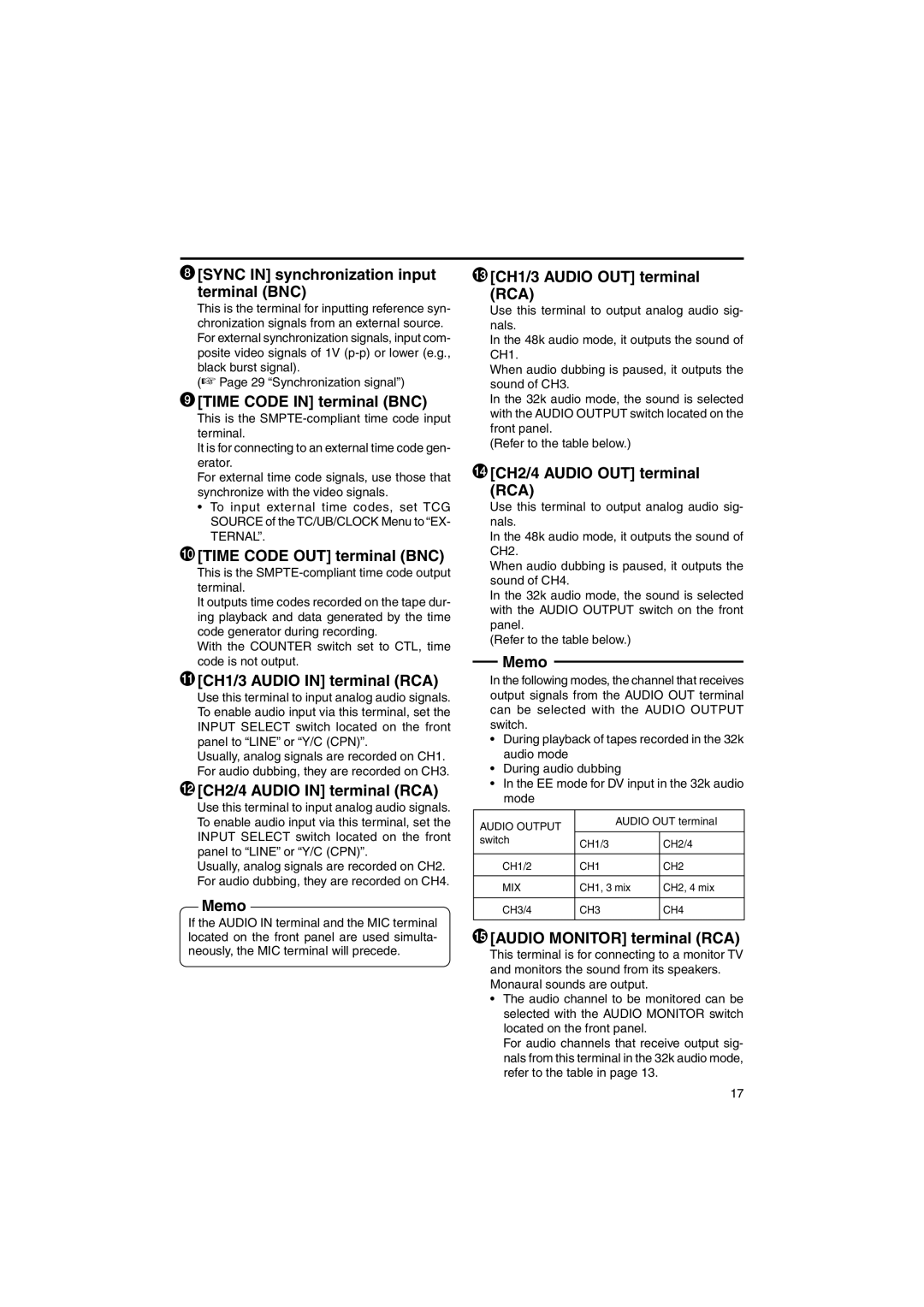
(Refer to the table below.)
$[CH2/4 AUDIO OUT] terminal
(RCA)
Use this terminal to output analog audio sig- nals.
In the 48k audio mode, it outputs the sound of CH2.
When audio dubbing is paused, it outputs the sound of CH4.
In the 32k audio mode, the sound is selected with the AUDIO OUTPUT switch on the front panel.
(Refer to the table below.)
Memo
In the following modes, the channel that receives output signals from the AUDIO OUT terminal can be selected with the AUDIO OUTPUT switch.
•During playback of tapes recorded in the 32k audio mode
•During audio dubbing
•In the EE mode for DV input in the 32k audio mode
AUDIO OUTPUT | AUDIO OUT terminal | |
|
| |
switch | CH1/3 | CH2/4 |
| ||
|
|
|
CH1/2 | CH1 | CH2 |
|
|
|
MIX | CH1, 3 mix | CH2, 4 mix |
|
|
|
CH3/4 | CH3 | CH4 |
|
|
|
%[AUDIO MONITOR] terminal (RCA)
This terminal is for connecting to a monitor TV and monitors the sound from its speakers. Monaural sounds are output.
•The audio channel to be monitored can be selected with the AUDIO MONITOR switch located on the front panel.
For audio channels that receive output sig- nals from this terminal in the 32k audio mode, refer to the table in page 13.
17
