RX-9010VBK
Mises en garde, précautions et indications diverses
For Canada/pour Le Canada
Table of Contents
Introduction
Features Precautions
Front Panel
Parts Identification
DVD MULTI, DVD, VCR 1, VCR 2, Video
AUDIO, FM/AM
TV/CATV/DBS POWER, VCR 1 Power 67
Remote Control
Checking the Supplied Accessories
Before Installation
Connecting the FM and AM Antennas
Getting Started
Basic connecting procedure
Connecting the Speakers
Connecting the front speakers
AM Antenna Connections
Connecting the rear and center speakers
Connecting Audio/Video Components
Connecting the subwoofer speaker
Analog Connections
CD recorder
Cassette deck or MD recorder
VCRs
Output to these video input jacks
SOUND/DBS, do not connect the TV’s video
To audio
Output
Digital output terminal
Digital Connections
Digital input terminals
USB Connection
Change the PC audio setting
Lamp on the USB Audio button lights up
USB cable
Rotate the fixing nut to attach the RF rod antenna firmly
Find the place where you attach the IR signal transmitter
Insert the RF rod antenna to the RF Remote Antenna terminal
Putting Batteries in the Remote Control
Connecting the Power Cord
Plug the power cord into an AC outlet
Replace the cover
Required Speaker Connections for the Sub-room
Multi-room Operations
Merits
Demerits
Press Power
Basic Operating Procedure for Main Room
Press Audio Power on
Select and play a source
Standby lamp on the front panel
Basic Operating Procedure for Sub-Room
Set Main ROOM/SUB Room selector to SUB Room
For the main room operations
Turning the Power On and Off Standby
Main Room Basic Operations
Selecting the Main Room Source to Play
Canceling the Main Room Operations
Selecting different sources for picture and sound
To stop the main room operations and sounds from the main
Speaker and signal indicators on the display
Adjusting the Main Room Volume
Speaker indicators
Signal indicators
Adjusting the Equalization Patterns
Attenuating the Input Signal
Listening at Night Midnight Mode Reinforcing the Bass
Activating the Subwoofer Sound
Muting the Main Room Sound
Recording a Source
Selecting the Line Direct Function Using the Sleep Timer
Changing the Display Brightness
Press SUB Room ON/OFF. SUB Room on /OFF
Sub-Room Operations
Press SUB Room CONTROL. SUB Room Control
For the sub-room operations
To turn off the power into standby mode, press
Canceling the Sub-room Operations
Audio Power Standby
SUB Room ON/OFF
To increase the volume, turn Master
Adjusting the Sub-room Volume
To decrease the volume, turn it counterclockwise
To increase the volume, press Volume +
Muting the Sub-room Sound
Activating the Sub-room Front Speakers
Through the front speaker in the sub Room
Operating the Playback Source for Sub-room
Setting the Front Speakers Either for Main Room or Sub-room
Basic Settings
Adjusting the Front Speaker Output Balance
To adjust the balance
Setting the Subwoofer Information
Adjusting the Subwoofer Output Level
Setting the Speakers for a Surround Field
To select the appropriate digital Terminal setting
Digital Input Digital in Terminal Setting
Cross Over appears on Display
Press Control UP 5/ Down Control
Selecting the Analog or Digital Input Mode
Terminal settings
Which you want to change the input mode
To set the Digital 2/3/4 terminals
To select the appropriate video Input terminal
Selecting the Video Input Terminal
Video DVD or Video DBS Appears on the display
Showing the Text Information on Display
Changing the Source Name
To store the volume level
Basic Setting and Adjustment Auto Memory
To recall the volume level
To cancel the One Touch Operation
Receiving Radio Broadcasts
Using Preset Tuning
Tuning in Stations Manually
Selecting the FM Reception Mode
DSP modes
Creating a Surround Field in the Main Room
Surround modes
Headphone DSP mode
DVD Multi Playback Mode
Reproducing the Sound Field
3D-PHONIC modes
Available DSP modes
Available DSP Modes According to the Speaker Arrangement
Theater \ Theater
Live Club \ Dance Club \ Pavilion
Adjusting the Surround Modes
Adjusting the DAP Modes
Adjust the center tone
Press Center Tone to select the center tone level you want
CTR Tone 1 CTR Tone 2 CTR Tone
Dance CLUB, or Pavilion appears on the display
Adjust the overall levels of the effect. Effect
Adjust the room size sense of spaciousness
Adjusting the Surround Modes with DAP Modes
Press DSP Mode repeatedly until DAP mode you want to adjust
Adjust the speaker output levels 10 dB to +10 dB
Press Effect to adjust the overall
Press Surround ON/OFF to Activate an appropriate Surround
Activate an appropriate Surround
Press DSP Mode repeatedly until
Adjust the liveness
Adjusting the 5 CH/4 CH Stereo Mode
Adjust the center tone for 5CH Stereo only
Center tone level you want for 5CH +10
Adjusting the 3D-PHONIC Modes
Stereo only
Center CTR Rearl Rearr
Press Center to select the center speaker
3D Action or 3D Digital
Activating the DVD Multi Playback Mode
Using the DVD Multi Playback Mode
Adjust the speaker output levels From -10 dB to +10 dB
Press DVD Multi so that DVD
Using the On-Screen Menus
Press %/ Þto move to Sound CONTROL, then press @/ #
Press %/ Þto move to the frequency you want to adjust
Press @/ #
Want
Press %/ Þto move to
Mode you want to
Select DVD Multi as the playing source
Press @/ #to turn
To Line Direct
Line direct function
On or OFF
Storing the Preset Stations Also see
Press %/ Þto move to SETTING, then press @/ #
Setting the Basic Setting Items
Press %/ Þto move to Tuner CONTROL, then press @/ #
Remote Control through the Remote Sensor on the Receiver
Compu Link Remote Control System
RX-9010VBK
Turntable
Synchronized Recording
Same time
Press the play 3 button on the CD player
CD player MD recorder
Text Compu Link Remote Control System
Displaying the Disc Information on the TV screen
Disc Search Only for CD Player
Disc Information screen
Press Text Display while CD or MD is selected as the source
Showing the Disc Information on the TV Screen
To exit from the Disc information screen
Press %/ Þto move to SEARCH, then press
Press Text Display while CD is selected as the source
Press %/ Þto move to Performer Then press SET
Press SET again
Press %/ Þto move To GENRE, then Press SET
Press %/ Þto move to SEARCH, then press SET
Press %/ Þto move To Title INPUT, then press SET
Entering the Disc Information
Press Text Display while MD is selected as the source
Press %/ Þto move to the genre you want, then press SET
Press %/ Þto move to Title Input Then press SET
For the MD recorder
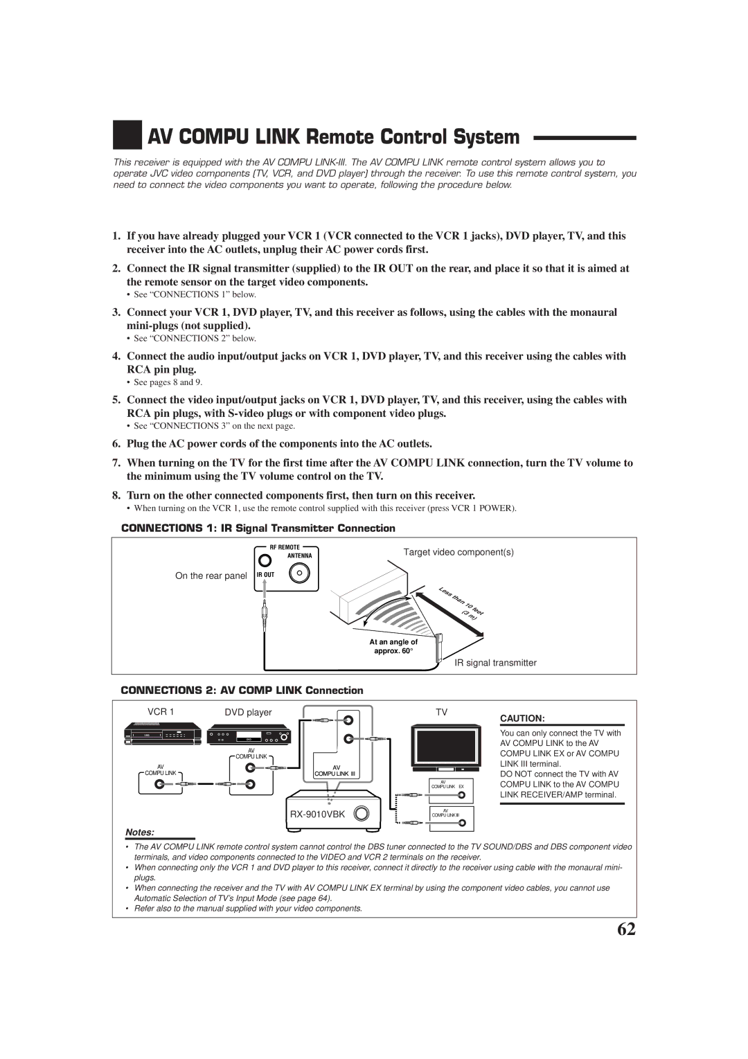
Connections 1 IR Signal Transmitter Connection
AV Compu Link Remote Control System
IR signal transmitter
Connections 2 AV Comp Link Connection
Connections 3 Video Cable Connection
To the TVs’ Video Input 1 terminal using S-video cables
Case
One-Touch Video Play
One-Touch DVD Play
Automatic Power On/Off Standby
Automatic Power On
Operating Audio Components
Operating JVC’s Audio/Video Components
Tuner
Sound control section Amplifier
CD recorder
CD player-changer
Turntable
Cassette deck
TV/CATV/DBS selector
Operating Video Components
Main ROOM/SUB Room selector
VCR VCR connected to the VCR 1 jacks
Release TV/CATV/DBS Power
Enter manufacturer’s code using buttons 1-9,
Operating Other Manufacturers’ Equipment
Try to operate your TV by pressing
Try to operate your VCR by pressing VCR 1 Power
Release VCR 1 Power
VCR 1 Power
If there are more than one code listed for your brand
If there are more than one code listed for your brand of CD
Release Audio Power on
Manufactures codes for TV Manufacturer Codes
Manufactures codes for DBS tuner Manufacturer Codes
Manufactures codes for VCR Manufacturer Codes
Manufactures codes for Catv converter Manufacturer Codes
Manufactures codes for DVD player Manufacturer Codes
Manufactures codes for CD player Manufacturer Codes
Problem Possible Cause Solution
Troubleshooting
CATV/DBS
Amplifier
Specifications
FM tuner IHF
AM tuner
Factory Service Center Locations
Qualityservice
781 954 650
Valley Road Wayne, NJ
Limited Warranty AUDIO-2
0201NHMMDWJEIN


 AV COMPU LINK Remote Control System