MSS User Guide | 2: Installation |
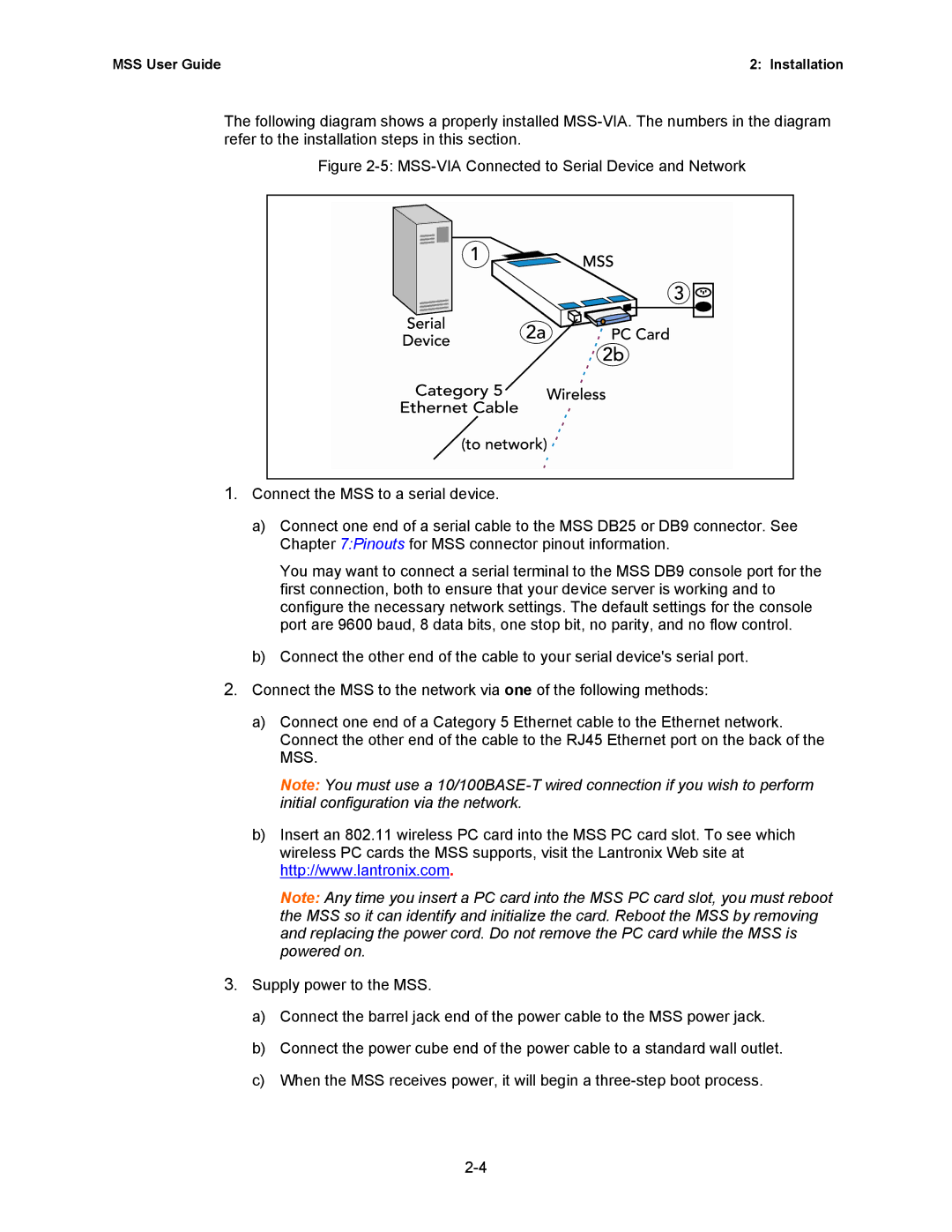
The following diagram shows a properly installed
Figure 2-5: MSS-VIA Connected to Serial Device and Network
1.Connect the MSS to a serial device.
a)Connect one end of a serial cable to the MSS DB25 or DB9 connector. See Chapter 7:Pinouts for MSS connector pinout information.
You may want to connect a serial terminal to the MSS DB9 console port for the first connection, both to ensure that your device server is working and to configure the necessary network settings. The default settings for the console port are 9600 baud, 8 data bits, one stop bit, no parity, and no flow control.
b)Connect the other end of the cable to your serial device's serial port.
2.Connect the MSS to the network via one of the following methods:
a)Connect one end of a Category 5 Ethernet cable to the Ethernet network. Connect the other end of the cable to the RJ45 Ethernet port on the back of the MSS.
Note: You must use a
b)Insert an 802.11 wireless PC card into the MSS PC card slot. To see which wireless PC cards the MSS supports, visit the Lantronix Web site at http://www.lantronix.com.
Note: Any time you insert a PC card into the MSS PC card slot, you must reboot the MSS so it can identify and initialize the card. Reboot the MSS by removing and replacing the power cord. Do not remove the PC card while the MSS is powered on.