Contents
MSS User Guide
Sales Offices
Lantronix Corporate Headquarters
Technical Support
Disclaimer & Revisions
Contents
Configuration
Using the MSS
Compliance and Warranty Information
Introduction to the MSS Family
MSS Family Features
Protocols
About The Documentation
Terms
MSS User Guide Introduction to the MSS Family
Components
Installation
MSS-VIA Installation
MSS-VIA LEDs
MSS-VIA Rear Panel
Example Wired Network Layout
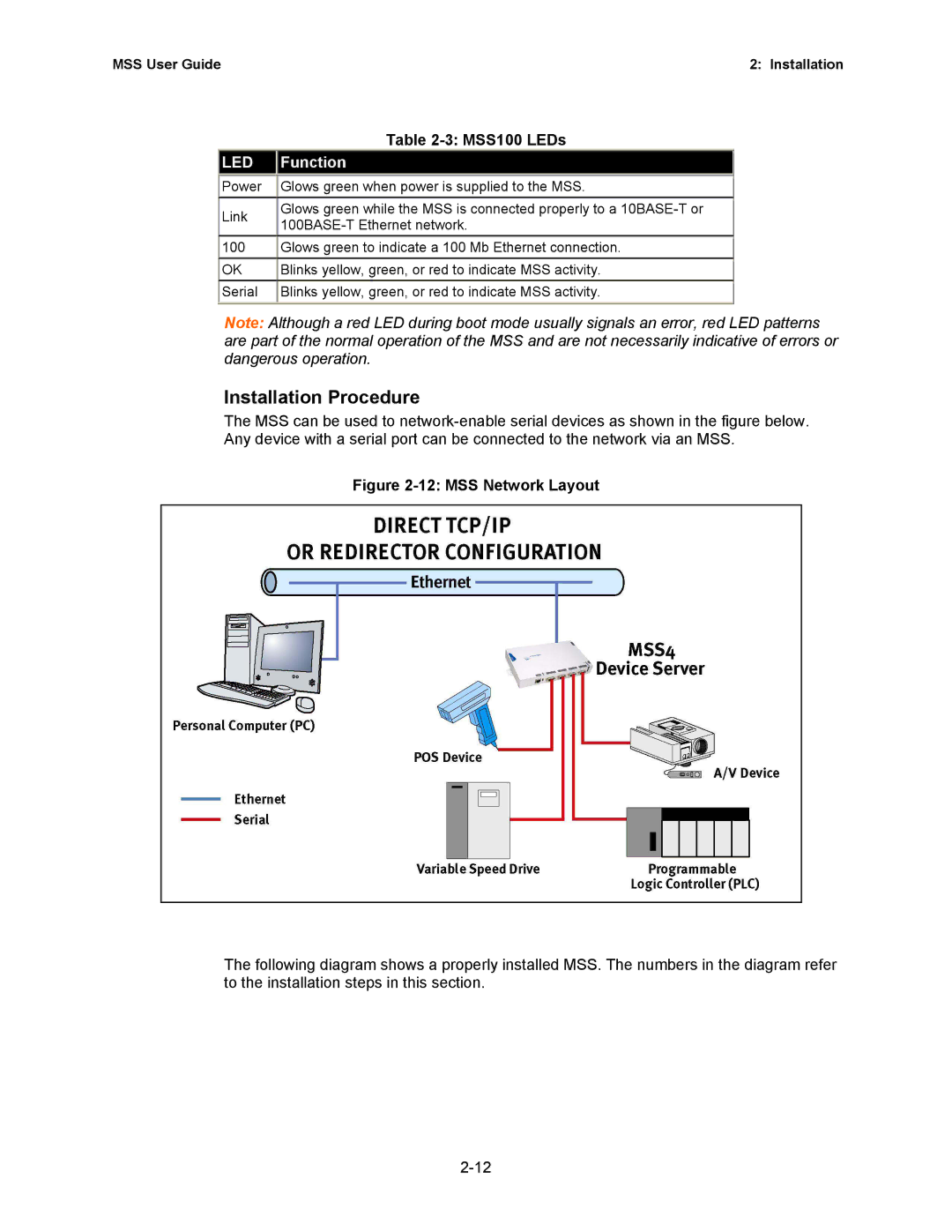
Installation Procedure
MSS User Guide Installation
Pinging the MSS
Humidity
MSS-VIA Specifications
Power power cube adaptor
Temperature
MSS4 Components
MSS4 Installation
MSS Connected to a Serial Device and Network
MSS4 LEDs
MSS User Guide Installation
MSS4 Specifications
10 MSS100 Front Panel
MSS100 Installation
12 MSS Network Layout
MSS100 LEDs
13 MSS Connected to Serial Device and Ethernet
14 Pinging the MSS
MSS100 Specifications
Privileged User Status
Getting Started
From the Action menu, select Assign IP Address
IP Address Configuration
Using EZWebCon
Using a Web Browser
Entering ARP and Ping Unix
Using ARP and Ping
Using the Serial Console
Using a DHCP, BOOTP, or Rarp Reply
Web Browser Login and Configuration
Incoming Logins
Login Password
Incoming TCP/IP Logins
Telnet
Serial Port Logins
EZWebCon Login and Configuration
Rlogin
Incoming LAT Logins
Changing the Login Password
Remote Console Logins
Logout
Outbound Connections
Overview
Configuration
Rebooting the MSS
Normal Reboot
TCP/IP Configuration
Protocol Configuration
Factory Defaults
Name Server
Specifying a Gateway for MSS-VIA and MSS4
Supported Mibs
IP Security
Routing and Encapsulation
IPX NetWare Configuration
Configuring Snmp
Snmp Trap Support
Loadhost
Internal Network Number
Server Identification
LAT Configuration
Service Groups
Circuit Timer
Two-Wire Mode
RS-485 Configuration
22 Enabling Two-Wire RS-485 Mode for MSS4
Four-Wire Mode
Termination
TXDrive
Autostart
Serial Port Configuration
Access Mode
Serial Data
36 Configuring an Autostart Character for MSS-VIA and MSS4
Character Size, Parity, and Stop Bits
Baud Rate
Flow Control
Modems and Modem Signaling
DSRLogout
Signal Checking
Modem Control
DTRWait
Logouts
Dedicated Host
Configuration
Preferred Host
Region
Enabling 802.11 Networking
MAC Address
Extended Service Set ID Essid
Channel
Network Mode
Setting the WEP Key and Index Number
Encrypted Traffic
Formatting an ATA Flash Card
Modem Cards
Outgoing Calls
Incoming Calls
Socket Connections
Using the MSS
Incoming Connections
TCP/IP Socket Connections
Interactive Connections
Outbound Connections
Session Control
Break Key and Local Switch
Backward, Forward, and Switches
Show
Status Displays
Disconnect and Resume
Session Limits
Serial Tunnel
UDP Configuration
TCP Configuration
Enabling Multihost Mode
Multihost Mode
Removing Hosts
Modem Emulation Mode
Adding Hosts
17. Enabling Modem Mode for MSS100
Modem Mode Commands
COM Port Redirector
Sequential Hostlist Mode
Wiring Requirements
Power-up Problems and Error Messages
Troubleshooting
Power-up Troubleshooting
Bootp Troubleshooting
Dhcp Troubleshooting
Bootp Troubleshooting
Dhcp Troubleshooting
Rarp Troubleshooting
Rarp Troubleshooting
Tftp Troubleshooting
Modem Configuration Checklist
Init
Entering Commands at the Boot Prompt
Change Bootp Enabled, Disabled
Change Loadhost ipaddress
Change Dhcp Enabled, Disabled
Change Hardware
Change Ipaddress ipaddress
Technical Support Europe, Middle East, and Africa
Technical Support
Pinouts
Ethernet Connector
MSS VIA Connectors
Serial Connectors
RS-485 DB9 Connectors
MSS4 Connectors
RS-232 DB9 Connector
RS-232 DB9 Connectors
MSS100 Connectors
DB25 Connector
DTR Data Terminal Ready
Modem Wiring
DSR Data Signal Ready versus CD Carrier Detect
Via the Web Via FTP
Updating Software
Obtaining Software
Reloading Software
FTP
NetWare
Troubleshooting Flash ROM Updates
Flash ROM Troubleshooting
MSS User Guide Updating Software
Compliance Information
Compliance and Warranty Information
Warranty