MSS User Guide | 2: Installation |
|
|
| Table |
| LED |
| Function |
| Serial |
| Blinks green to indicate MSS serial activity. |
| |||
|
| ||
| OK | Blinks yellow, green, or red to indicate MSS activity. | |
|
|
| Glows green or yellow to indicate a wired Ethernet connection. |
| Link |
| Off: Not connected to a wired Ethernet network |
|
| Green: Connected to a | |
|
|
| |
|
|
| Yellow: Connected to either a |
Installation Procedure
The MSS should be positioned close to the device it will be servicing. Since powering down the unit will terminate any active sessions, it may be desirable to place the device server in a location secure from user access. Also be aware of the unit’s environmental operating limits and cabling requirements.
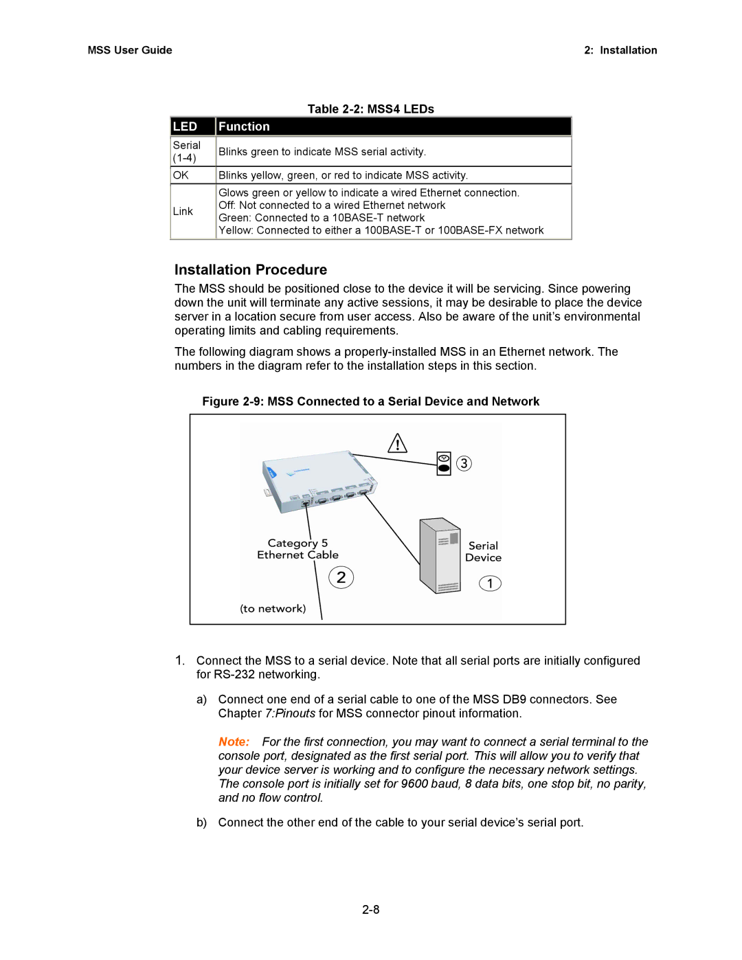
The following diagram shows a
Figure 2-9: MSS Connected to a Serial Device and Network
1.Connect the MSS to a serial device. Note that all serial ports are initially configured for
a)Connect one end of a serial cable to one of the MSS DB9 connectors. See Chapter 7:Pinouts for MSS connector pinout information.
Note: For the first connection, you may want to connect a serial terminal to the console port, designated as the first serial port. This will allow you to verify that your device server is working and to configure the necessary network settings. The console port is initially set for 9600 baud, 8 data bits, one stop bit, no parity, and no flow control.
b)Connect the other end of the cable to your serial device’s serial port.