Section 3
SOFTWARE OPERATION |
3.1 SYNERGIC WELDING AND WORKPOINTS
Prior to using Wave Designer it is important to have a good understanding of the concepts of synergic welding and workpoints. Synergic welding is basically “one knob control” of a welding process; all other variables of the process are adjusted by the power source based on the single controlling variable. This single controlling variable is known as a workpoint. For example, in synergic pulse welding
Wave Designer is a program that lets you develop a customized weld procedure by letting you program each variable for multiple workpoints into a weld “look up” table.
Power Wave power sources go even a step further than simply “looking up”
Refering to Figure
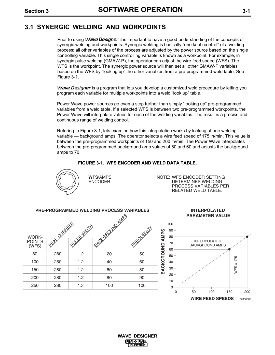
FIGURE 3-1. WFS ENCODER AND WELD DATA TABLE.
WFS/AMPS | NOTE: WFS ENCODER SETTING |
ENCODER | DETERMINES WELDING |
| PROCESS VARIABLES PER |
| RELATED WELD TABLE. |
|
| PULSE | WIDTH | BACKGROUND | AMPS | |
(WFS) |
|
|
| |||
WORK- |
|
|
|
|
|
|
POINTS |
|
|
|
|
|
|
|
|
|
|
|
| |
80 | 280 | 1.2 | 20 |
| 50 | |
|
|
|
|
|
| |
100 | 280 | 1.2 | 40 |
| 60 | |
|
|
|
|
|
| |
150 | 280 | 1.2 | 60 |
| 80 | |
|
|
|
|
|
| |
200 | 280 | 1.2 | 80 |
| 90 | |
|
|
|
|
|
| |
250 | 280 | 1.2 | 100 |
| 100 | |
|
|
|
|
|
|
|
BACKGROUND AMPS
100
90
80
70
60
50
40
30
20
10
0
0
INTERPOLATED
PARAMETER VALUE
| INTERPOLATED |
|
|
|
|
| ||
BACKGROUND AMPS |
|
|
|
|
| |||
|
|
|
|
|
| WFS = 175 |
|
|
|
|
|
|
|
|
|
| |
|
|
|
|
|
|
|
| |
|
|
|
|
|
|
|
|
|
50 | 100 | 150 | 200 | |||||
WIRE FEED SPEEDS | 27850005 | |||||||
WAVE DESIGNER