Appendix A | PULSE WAVE SHAPING PRINCIPLES |
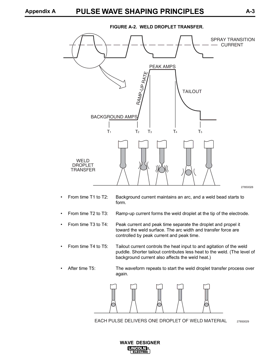
FIGURE A-2. WELD DROPLET TRANSFER.
SPRAY TRANSITION
CURRENT
PEAK AMPS
TAILOUT
BACKGROUND AMPS
T1 | T2 | T3 | T4 | T5 |
WELD
DROPLET
TRANSFER
•From time T1 to T2:
•From time T2 to T3:
•From time T3 to T4:
27850028
Background current maintains an arc, and a weld bead starts to form.
Peak current and peak time separate the droplet and propel it toward the weld surface. The arc width and transfer force are controlled by peak current and peak time.
• | From time T4 to T5: | Tailout current controls the heat input to and agitation of the weld | |||||||||
|
| puddle. Shorter tailout contributes less heat to the weld. (The level of | |||||||||
|
| background current also affects the weld heat.) | |||||||||
• | After time T5: | The waveform repeats to start the weld droplet transfer process over | |||||||||
|
| again. | |||||||||
|
|
|
|
|
|
|
|
|
|
|
|
|
|
|
|
|
|
|
|
|
|
|
|
EACH PULSE DELIVERS ONE DROPLET OF WELD MATERIAL | 27850029 |
WAVE DESIGNER