Appendix A | PULSE WAVE SHAPING PRINCIPLES |
A.4 PULSE WAVE DESIGN PROCESS
The Wave Designer software interfaces with the welding machine controller to permit real time communication of pulse wave design changes. Refer to paragraph 2.3 for equipment interface connections.
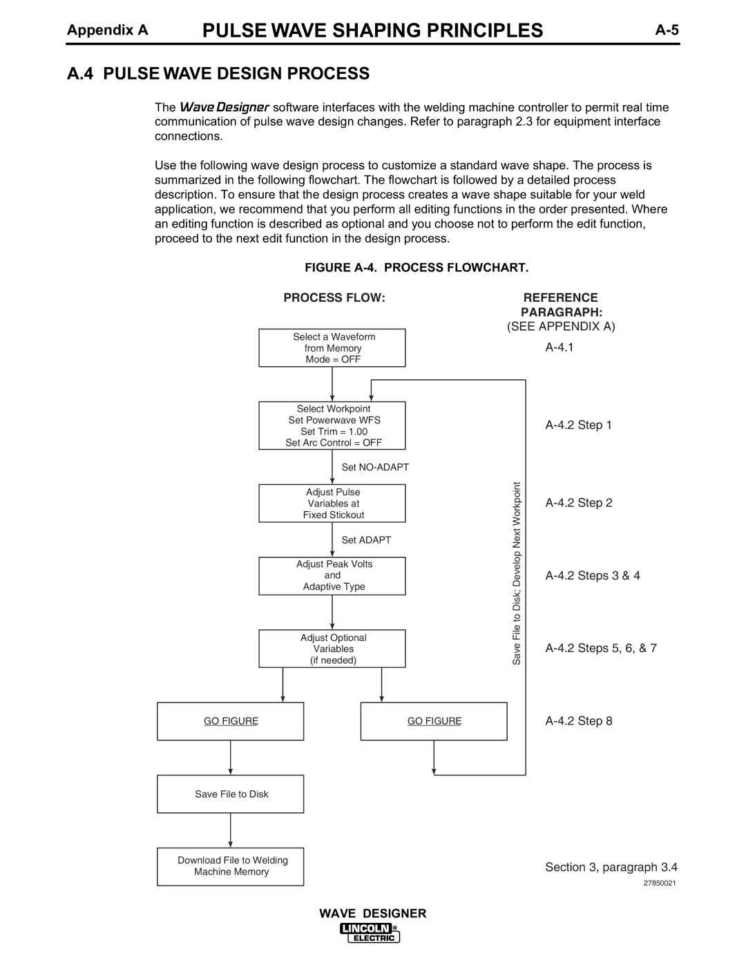
Use the following wave design process to customize a standard wave shape. The process is summarized in the following flowchart. The flowchart is followed by a detailed process description. To ensure that the design process creates a wave shape suitable for your weld application, we recommend that you perform all editing functions in the order presented. Where an editing function is described as optional and you choose not to perform the edit function, proceed to the next edit function in the design process.
FIGURE A-4. PROCESS FLOWCHART.
PROCESS FLOW:
Select a Waveform
from Memory
Mode = OFF
REFERENCE
PARAGRAPH: (SEE APPENDIX A)
Select Workpoint |
| |
Set Powerwave WFS |
| |
Set Trim = 1.00 |
| |
Set Arc Control = OFF |
| |
Set | ||
Adjust Pulse | Workpoint | |
| ||
Variables at |
| |
Fixed Stickout | Next | |
Set ADAPT | ||
Develop | ||
Adjust Peak Volts | ||
| ||
and |
| |
Adaptive Type | File to Disk; | |
Adjust Optional | ||
Save | ||
(if needed) | ||
Variables |
| |
GO FIGURE | GO FIGURE | |
Save File to Disk
Download File to Welding Machine Memory
Section 3, paragraph 3.4
27850021
WAVE DESIGNER