PULSE WAVE SHAPING PRINCIPLES | Appendix A |
2. Open the Adaptive Loop / Find the Optimal Arc Characteristics
Use the following weld trials and adjustment sequence to tune the selected waveform for your weld application at the designated workpoint (wire feed speed). Weld trials and adjustments are more easily performed with one person welding while you adjust the waveform parameters at the computer terminal.
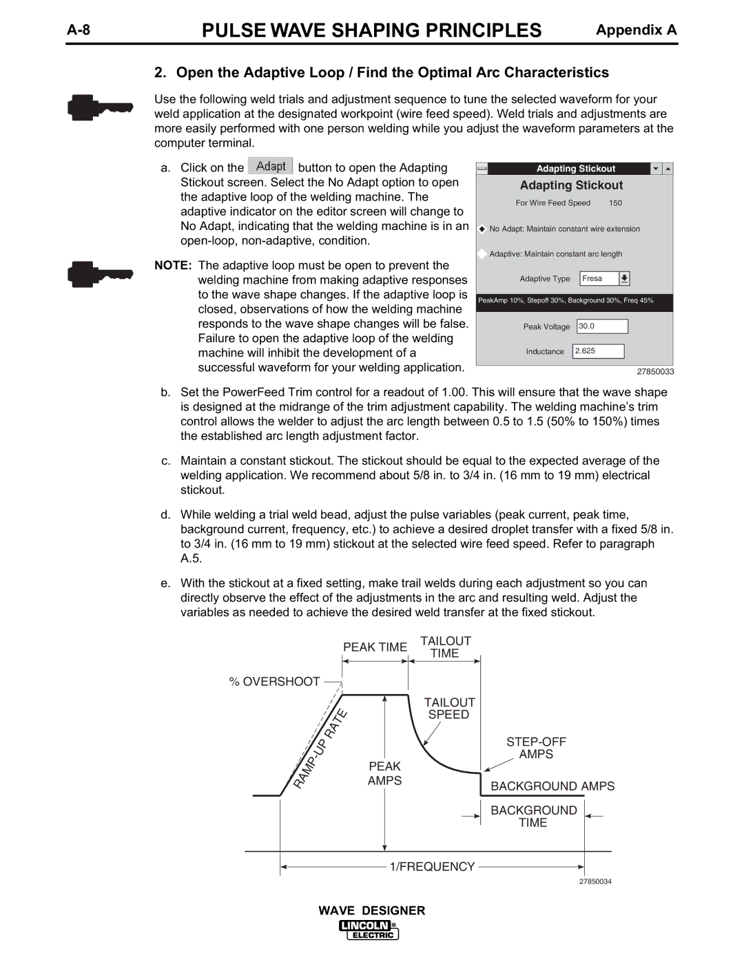
a.Click on the ![]() button to open the Adapting Stickout screen. Select the No Adapt option to open the adaptive loop of the welding machine. The adaptive indicator on the editor screen will change to No Adapt, indicating that the welding machine is in an
button to open the Adapting Stickout screen. Select the No Adapt option to open the adaptive loop of the welding machine. The adaptive indicator on the editor screen will change to No Adapt, indicating that the welding machine is in an
NOTE: The adaptive loop must be open to prevent the welding machine from making adaptive responses to the wave shape changes. If the adaptive loop is closed, observations of how the welding machine responds to the wave shape changes will be false. Failure to open the adaptive loop of the welding machine will inhibit the development of a successful waveform for your welding application.
Adapting Stickout
Adapting Stickout
For Wire Feed Speed 150
![]() No Adapt: Maintain constant wire extension
No Adapt: Maintain constant wire extension
![]() Adaptive: Maintain constant arc length
Adaptive: Maintain constant arc length
Adaptive Type Fresa
PeakAmp 10%, Stepoff 30%, Background 30%, Freq 45%
Peak Voltage 30.0
Inductance 2.625
27850033
b.Set the PowerFeed Trim control for a readout of 1.00. This will ensure that the wave shape is designed at the midrange of the trim adjustment capability. The welding machine’s trim control allows the welder to adjust the arc length between 0.5 to 1.5 (50% to 150%) times the established arc length adjustment factor.
c.Maintain a constant stickout. The stickout should be equal to the expected average of the welding application. We recommend about 5/8 in. to 3/4 in. (16 mm to 19 mm) electrical stickout.
d.While welding a trial weld bead, adjust the pulse variables (peak current, peak time, background current, frequency, etc.) to achieve a desired droplet transfer with a fixed 5/8 in. to 3/4 in. (16 mm to 19 mm) stickout at the selected wire feed speed. Refer to paragraph A.5.
e.With the stickout at a fixed setting, make trail welds during each adjustment so you can directly observe the effect of the adjustments in the arc and resulting weld. Adjust the variables as needed to achieve the desired weld transfer at the fixed stickout.
PEAK TIME
% OVERSHOOT ![]()
PEAK
AMPS
TAILOUT
TIME
TAILOUT SPEED
AMPS
BACKGROUND AMPS
BACKGROUND
TIME
1/FREQUENCY
27850034
WAVE DESIGNER