PULSE WAVE SHAPING PRINCIPLES | Appendix A |
8.For a second workpoint we went to 300 in/min. Select the 300 in/min. wire feed speed from the pulldown menu in Waveform Editor window. Reset the PowerFeed for 300 in/min. with a 1.00 trim.
9.Open the adapting stickout window and select the ‘No Adapt’ mode; close the window.
10.At lower wire feed speed settings, some users like to fix the values of the peak variables. To do this, check the boxes next to the peak variables (ramp up rate, ramp overshoot %, peak amps, peak time, and tailout). Perform weld trials and adjust the pulse wave shape variables.
Our Experiment: At the higher wire feed speed, we needed more heat to melt the added wire. We took the background up to 75 amps and the background time down to
3.8milliseconds. (The frequency also changed due to the change to the background time.) Welding trials indicated that the droplets were transferring properly and that the arc length was correct for the 5/8 in. (16 mm) stickout.
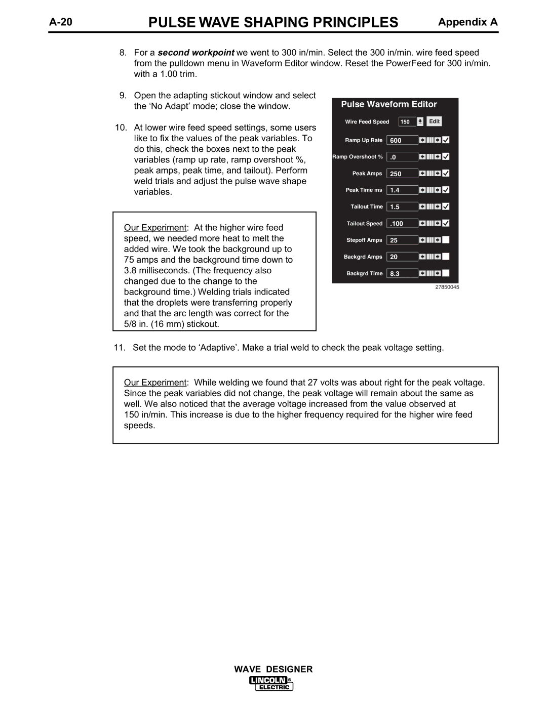
Pulse Waveform Editor
Wire Feed Speed | 150 | Edit |
Ramp Up Rate | 600 |
|
Ramp Overshoot % | .0 |
|
Peak Amps | 250 |
|
Peak Time ms | 1.4 |
|
Tailout Time | 1.5 |
|
Tailout Speed | .100 |
|
Stepoff Amps | 25 |
|
Backgrd Amps | 20 |
|
Backgrd Time | 8.3 |
|
27850045
11. Set the mode to ‘Adaptive’. Make a trial weld to check the peak voltage setting.
Our Experiment: While welding we found that 27 volts was about right for the peak voltage. Since the peak variables did not change, the peak voltage will remain about the same as well. We also noticed that the average voltage increased from the value observed at
150 in/min. This increase is due to the higher frequency required for the higher wire feed speeds.
WAVE DESIGNER