MAINTENANCE |
Return to Master TOC
Return to Master TOC
GENERATOR/WELDER MAINTENANCE
STORAGE: Store the POWERARC® 5500 in clean, dry, protected areas.
CLEANING: Blow out the generator and controls periodically with low pressure air. Do this at least once a week in particularly dirty areas.
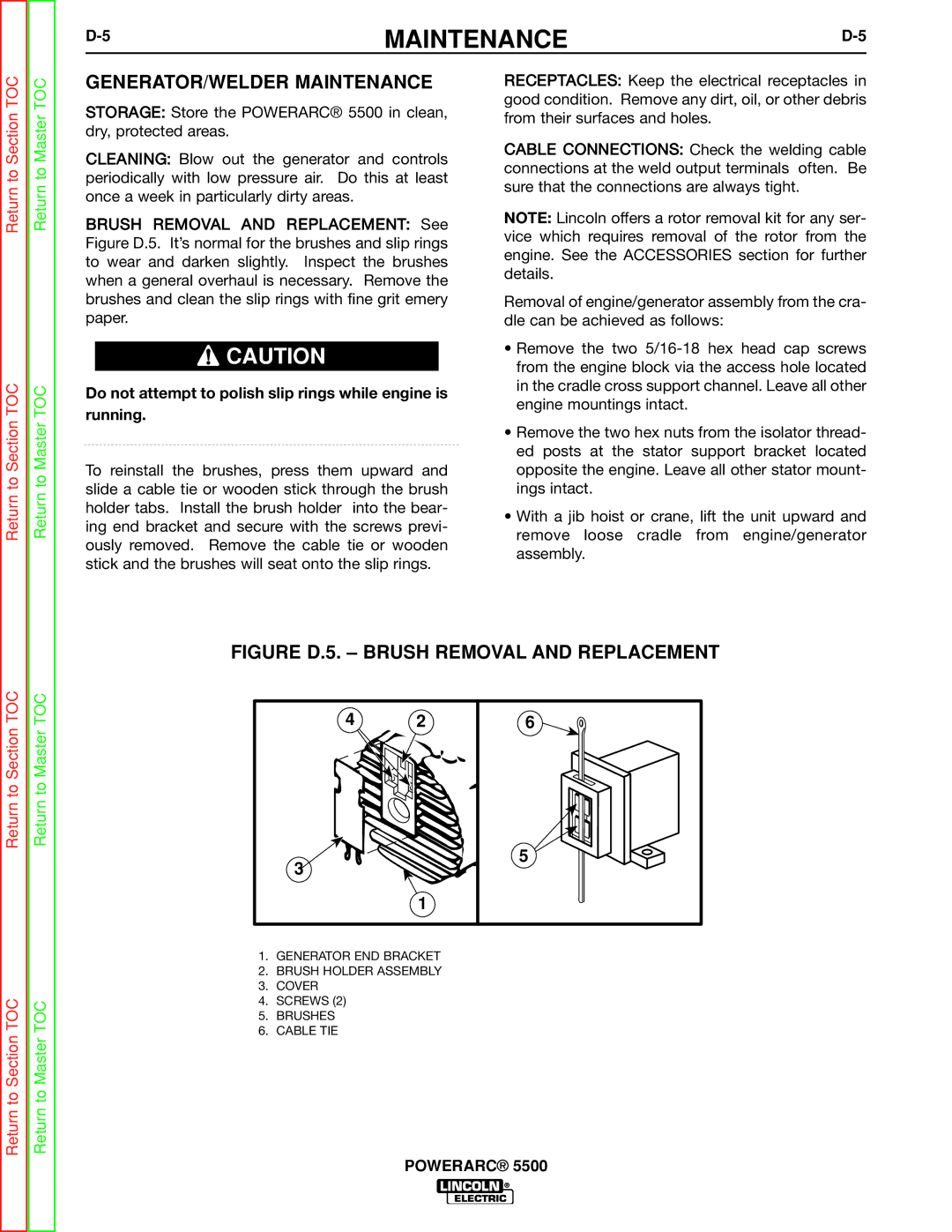
BRUSH REMOVAL AND REPLACEMENT: See Figure D.5. It’s normal for the brushes and slip rings to wear and darken slightly. Inspect the brushes when a general overhaul is necessary. Remove the brushes and clean the slip rings with fine grit emery paper.
![]() CAUTION
CAUTION
Do not attempt to polish slip rings while engine is running.
To reinstall the brushes, press them upward and slide a cable tie or wooden stick through the brush holder tabs. Install the brush holder into the bear- ing end bracket and secure with the screws previ- ously removed. Remove the cable tie or wooden stick and the brushes will seat onto the slip rings.
RECEPTACLES: Keep the electrical receptacles in good condition. Remove any dirt, oil, or other debris from their surfaces and holes.
CABLE CONNECTIONS: Check the welding cable connections at the weld output terminals often. Be sure that the connections are always tight.
NOTE: Lincoln offers a rotor removal kit for any ser- vice which requires removal of the rotor from the engine. See the ACCESSORIES section for further details.
Removal of engine/generator assembly from the cra- dle can be achieved as follows:
•Remove the two
•Remove the two hex nuts from the isolator thread- ed posts at the stator support bracket located opposite the engine. Leave all other stator mount- ings intact.
•With a jib hoist or crane, lift the unit upward and remove loose cradle from engine/generator assembly.
Return to Section TOC
Return to Section TOC
FIGURE D.5. – BRUSH REMOVAL AND REPLACEMENT
Return to Section TOC
Return to Master TOC
42
3 |
1
6 |
5 |
Return to Section TOC
Return to Master TOC
1.GENERATOR END BRACKET
2.BRUSH HOLDER ASSEMBLY
3.COVER
4.SCREWS (2)
5.BRUSHES
6.CABLE TIE