Return to Section TOC
Return to Section TOC
Return to Master TOC
Return to Master TOC
THEORY OF OPERATION | ||
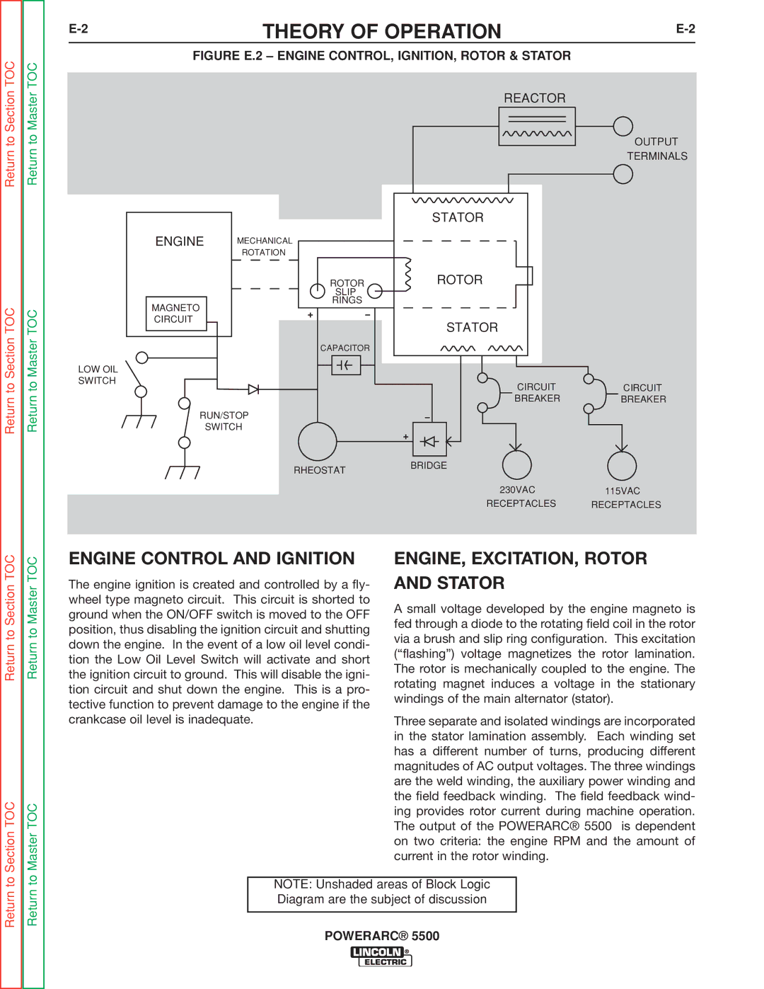
| FIGURE E.2 – ENGINE CONTROL, IGNITION, ROTOR & STATOR |
|
|
| REACTOR |
|
|
|
| OUTPUT |
|
|
| TERMINALS |
|
| STATOR |
|
ENGINE | MECHANICAL |
|
|
| ROTATION |
|
|
| ROTOR | ROTOR |
|
| SLIP |
|
|
MAGNETO | RINGS |
|
|
|
|
| |
CIRCUIT |
| STATOR |
|
|
|
| |
| CAPACITOR |
|
|
LOW OIL |
|
|
|
SWITCH |
| CIRCUIT | CIRCUIT |
|
| ||
|
| BREAKER | BREAKER |
RUN/STOP |
|
| |
| SWITCH |
|
|
| RHEOSTAT | BRIDGE |
|
|
|
| |
|
| 230VAC | 115VAC |
|
| RECEPTACLES | RECEPTACLES |
Return to Section TOC
Section TOC
Return to Master TOC
Master TOC
ENGINE CONTROL AND IGNITION
The engine ignition is created and controlled by a fly- wheel type magneto circuit. This circuit is shorted to ground when the ON/OFF switch is moved to the OFF position, thus disabling the ignition circuit and shutting down the engine. In the event of a low oil level condi- tion the Low Oil Level Switch will activate and short the ignition circuit to ground. This will disable the igni- tion circuit and shut down the engine. This is a pro- tective function to prevent damage to the engine if the crankcase oil level is inadequate.
ENGINE, EXCITATION, ROTOR AND STATOR
A small voltage developed by the engine magneto is fed through a diode to the rotating field coil in the rotor via a brush and slip ring configuration. This excitation (“flashing”) voltage magnetizes the rotor lamination. The rotor is mechanically coupled to the engine. The rotating magnet induces a voltage in the stationary windings of the main alternator (stator).
Three separate and isolated windings are incorporated in the stator lamination assembly. Each winding set has a different number of turns, producing different magnitudes of AC output voltages. The three windings are the weld winding, the auxiliary power winding and the field feedback winding. The field feedback wind- ing provides rotor current during machine operation. The output of the POWERARC® 5500 is dependent on two criteria: the engine RPM and the amount of current in the rotor winding.
Return to
NOTE: Unshaded areas of Block Logic Diagram are the subject of discussion