Return to Section TOC
Return to Section TOC
Return to Section TOC
Return to Section TOC
Return to Master TOC
Return to Master TOC
Return to Master TOC
Return to Master TOC
TROUBLESHOOTING AND REPAIR |
ROTOR RESISTANCE TEST PROCEDURE (continued)
ROTOR RESISTANCE TEST (continued)
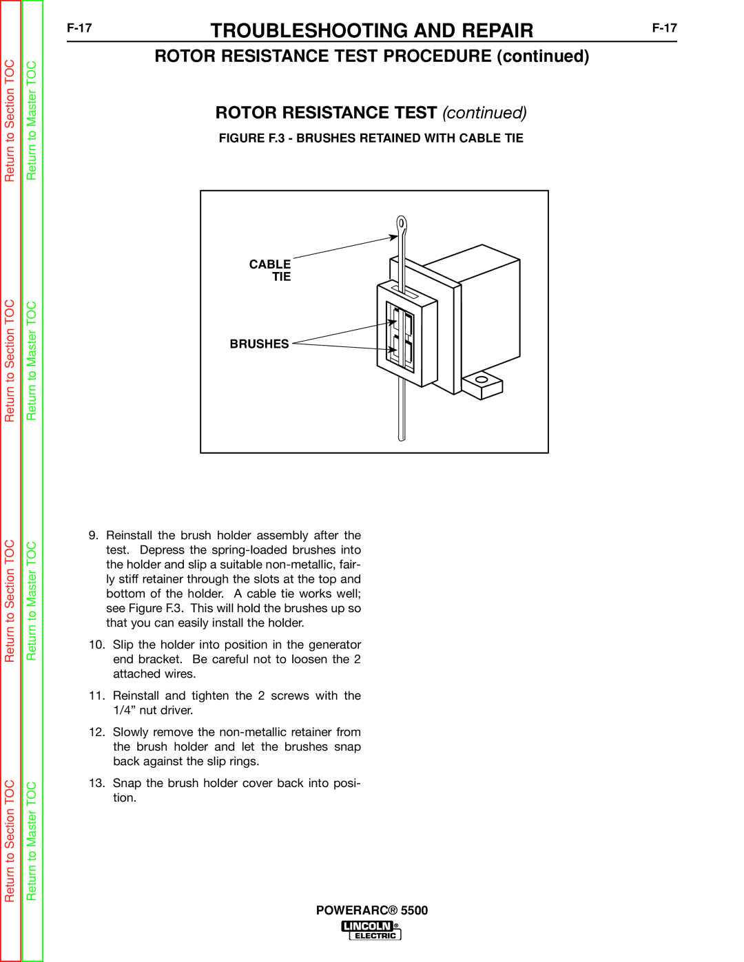
FIGURE F.3 - BRUSHES RETAINED WITH CABLE TIE
CABLE
TIE
BRUSHES ![]()
![]()
9.Reinstall the brush holder assembly after the test. Depress the
10.Slip the holder into position in the generator end bracket. Be careful not to loosen the 2 attached wires.
11.Reinstall and tighten the 2 screws with the 1/4” nut driver.
12.Slowly remove the
13.Snap the brush holder cover back into posi- tion.