Return to Section TOC
Return to Section TOC
Section TOC
Return to Master TOC
Return to Master TOC
Master TOC
THEORY OF OPERATION | ||
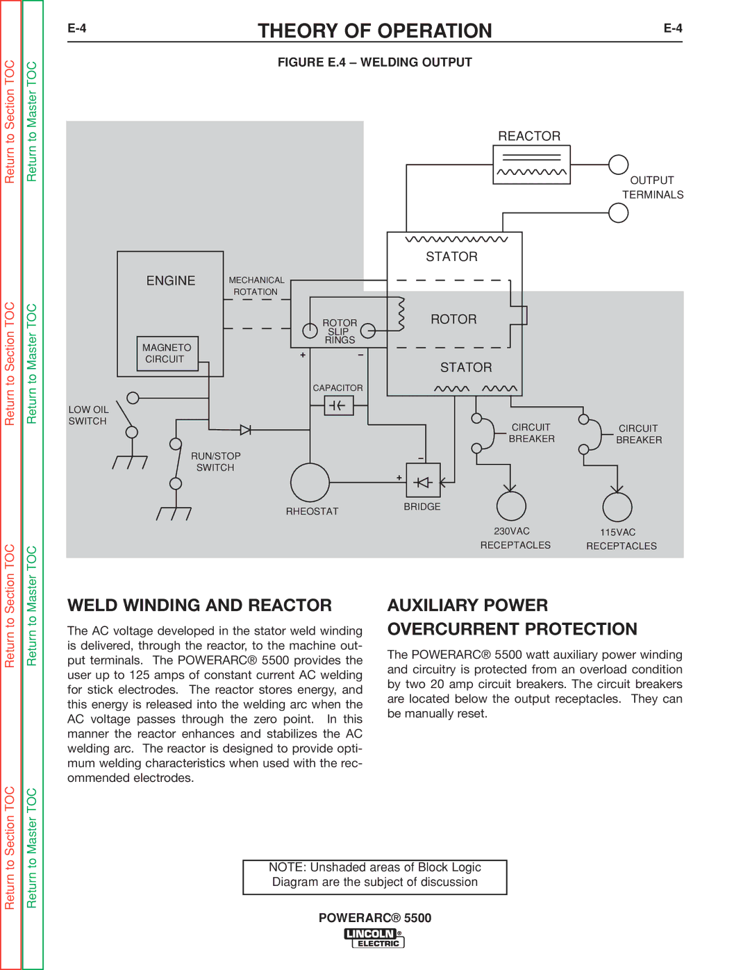
| FIGURE E.4 – WELDING OUTPUT |
|
|
| REACTOR |
|
|
|
| OUTPUT |
|
|
| TERMINALS |
|
| STATOR |
|
ENGINE | MECHANICAL |
|
|
| ROTATION |
|
|
| ROTOR | ROTOR |
|
| SLIP |
|
|
MAGNETO | RINGS |
|
|
|
|
| |
CIRCUIT |
| STATOR |
|
|
|
| |
| CAPACITOR |
|
|
LOW OIL |
|
|
|
SWITCH |
| CIRCUIT | CIRCUIT |
|
| ||
|
| BREAKER | BREAKER |
RUN/STOP |
|
| |
| SWITCH |
|
|
| RHEOSTAT | BRIDGE |
|
|
|
| |
|
| 230VAC | 115VAC |
|
| RECEPTACLES | RECEPTACLES |
Return to
WELD WINDING AND REACTOR
The AC voltage developed in the stator weld winding is delivered, through the reactor, to the machine out- put terminals. The POWERARC® 5500 provides the user up to 125 amps of constant current AC welding for stick electrodes. The reactor stores energy, and this energy is released into the welding arc when the AC voltage passes through the zero point. In this manner the reactor enhances and stabilizes the AC welding arc. The reactor is designed to provide opti- mum welding characteristics when used with the rec- ommended electrodes.
AUXILIARY POWER OVERCURRENT PROTECTION
The POWERARC® 5500 watt auxiliary power winding and circuitry is protected from an overload condition by two 20 amp circuit breakers. The circuit breakers are located below the output receptacles. They can be manually reset.
Return to Section TOC
Return to Master TOC
NOTE: Unshaded areas of Block Logic Diagram are the subject of discussion