1.3.2 Rear View
25 | 26 | 27 | 28 | 29 | 31 |
| FROM MUX |
|
VIDEO | MAIN MONITOR |
|
| AUDIO | |
IN | IN | |
|
| ETHERNET |
|
| 10/100 |
OUT | OUT | |
| ||
TO | TO |
|
MUX'S VCR IN | MONITOR |
|
ALARM I/O | DC12V |
|
32 | 33 | 34 | 35 | 37 | 38 36 |
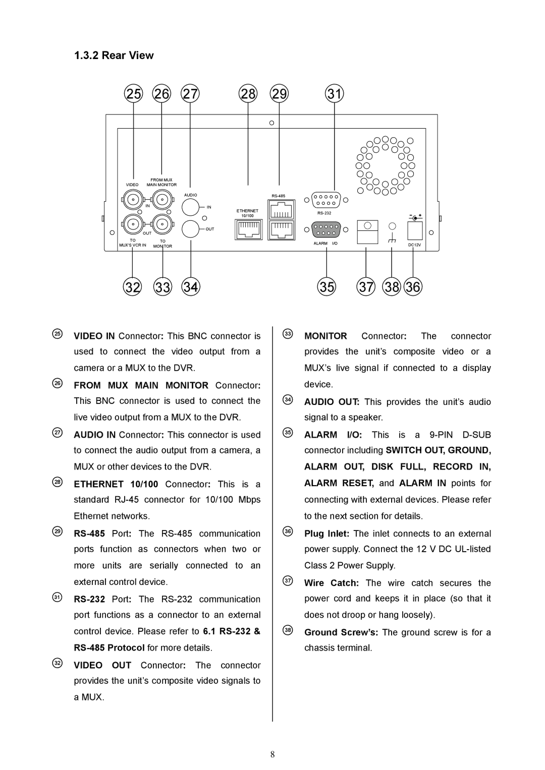
25VIDEO IN Connector: This BNC connector is used to connect the video output from a camera or a MUX to the DVR.
26FROM MUX MAIN MONITOR Connector: This BNC connector is used to connect the live video output from a MUX to the DVR.
27AUDIO IN Connector: This connector is used to connect the audio output from a camera, a MUX or other devices to the DVR.
28ETHERNET 10/100 Connector: This is a standard
29
31
32VIDEO OUT Connector: The connector provides the unit’s composite video signals to a MUX.
33
34
35
36
37
38
MONITOR Connector: The connector provides the unit’s composite video or a MUX’s live signal if connected to a display device.
AUDIO OUT: This provides the unit’s audio signal to a speaker.
ALARM I/O: This is a
ALARM OUT, DISK FULL, RECORD IN, ALARM RESET, and ALARM IN points for connecting with external devices. Please refer to the next section for details.
Plug Inlet: The inlet connects to an external power supply. Connect the 12 V DC
Wire Catch: The wire catch secures the power cord and keeps it in place (so that it does not droop or hang loosely).
Ground Screw’s: The ground screw is for a chassis terminal.
8