1.4 ALARM In / Out
|
|
|
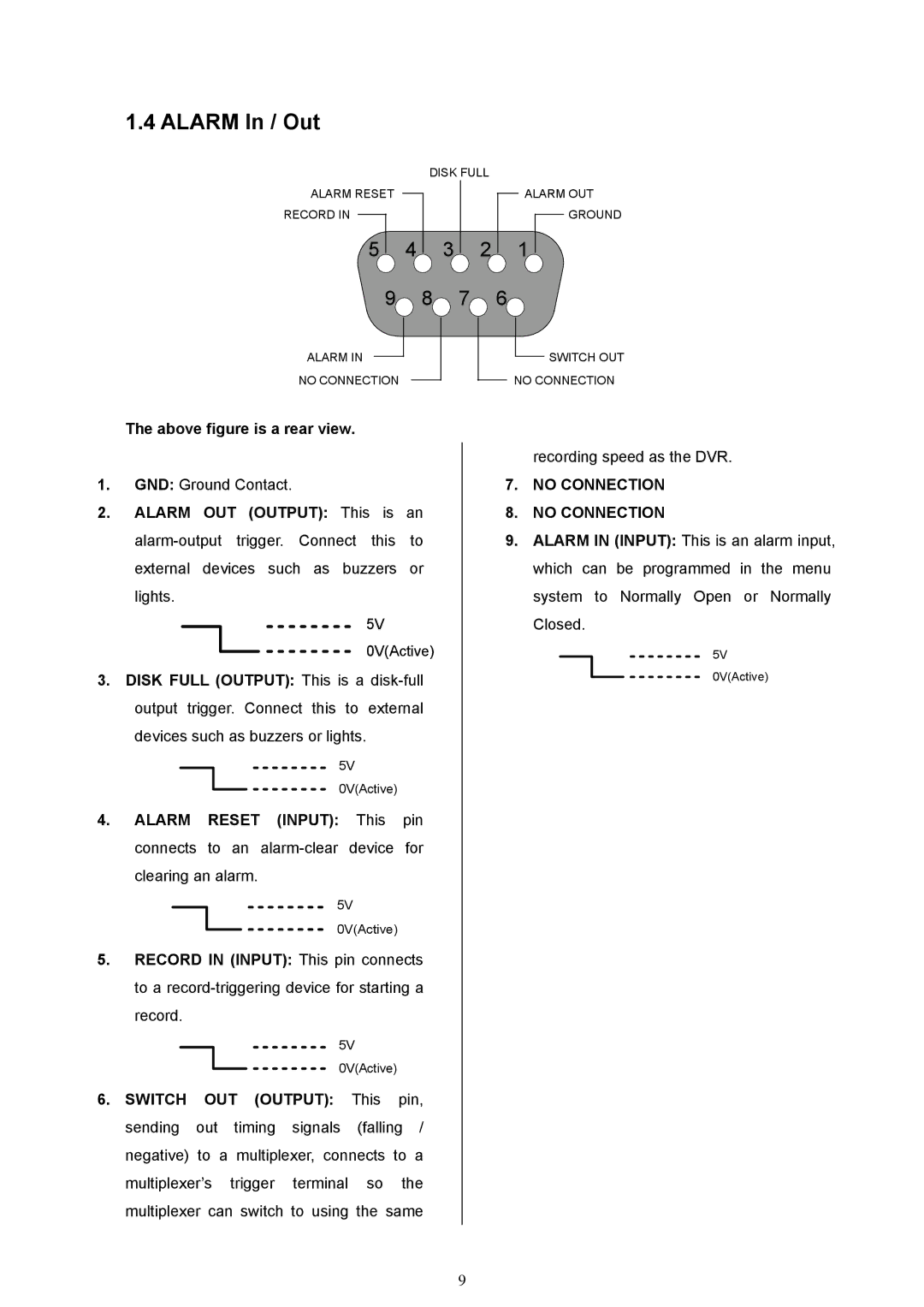
| DISK FULL | ||||
ALARM RESET |
|
|
| ALARM OUT | ||||
|
| |||||||
RECORD IN |
|
|
|
|
|
|
| GROUND |
|
|
|
|
| ||||
5 4 3 2 1
9 8 7 6![]()
ALARM IN
NO CONNECTION
SWITCH OUT NO CONNECTION
The above figure is a rear view.
1.GND: Ground Contact.
2.ALARM OUT (OUTPUT): This is an
5V
0V(Active)
3.DISK FULL (OUTPUT): This is a
5V
0V(Active)
4.ALARM RESET (INPUT): This pin connects to an
5V
0V(Active)
5.RECORD IN (INPUT): This pin connects to a
5V
0V(Active)
6.SWITCH OUT (OUTPUT): This pin, sending out timing signals (falling / negative) to a multiplexer, connects to a multiplexer’s trigger terminal so the multiplexer can switch to using the same
recording speed as the DVR.
7.NO CONNECTION
8.NO CONNECTION
9.ALARM IN (INPUT): This is an alarm input, which can be programmed in the menu system to Normally Open or Normally Closed.
5V
0V(Active)
9