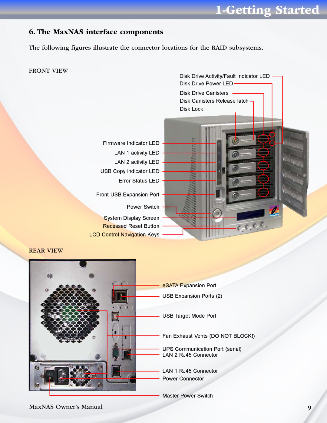
Firmware Indicator LED LAN 1 activity LED LAN 2 activity LED
USB Copy indicator LED Error Status LED
Front USB Expansion Port Power Switch
System Display Screen
Recessed Reset Button LCD Control Navigation Keys
REAR VIEW
MaxNAS Owner’s Manual
6. The MaxNAS interface components
The following figures illustrate the connector locations for the RAID subsystems.
FRONT VIEW
Disk Drive Activity/Fault Indicator LED Disk Drive Power LED
Disk Drive Canisters
Disk Canisters Release latch Disk Lock
1-Getting Started
eSATA Expansion Port
USB Expansion Ports (2)
USB Target Mode Port
Fan Exhaust Vents (DO NOT BLOCK!)
UPS Communication Port (serial) LAN 2 RJ45 Connector
LAN 1 RJ45 Connector
Power Connector
Master Power Switch
9