DX-TL2500U
Page
Avertissement
Important safeguards
Servicing
Damage requiring Service
Replacement Parts
Safety Check
When not in use always turn OFF the Main switch
Protect the Power Cord
Recordable time and product warranty
Network
Features
Built-in duplex 16 channel multiplexer
Recording
Auto set-up
Wired Remote Controller Optional
Ease of use
PTZ camera control
Contents
80,81
67-71
73,74
75-79
Flowchart for connection and settings
Flowchart
Auto SET UP
Timer recording is executed/completed
Setting other various functions
Setting the motion detection
Setting the timer recording
Major operations and their functions
Power button
SET UP button
Analogue OUT connectors
Alarm Interrupt button
Major operations and their functions
Audio connectors
Main switch
Camera OUT connectors
Camera in connectors
Power Cord
Connecting to Cctv camera, monitor, sensor
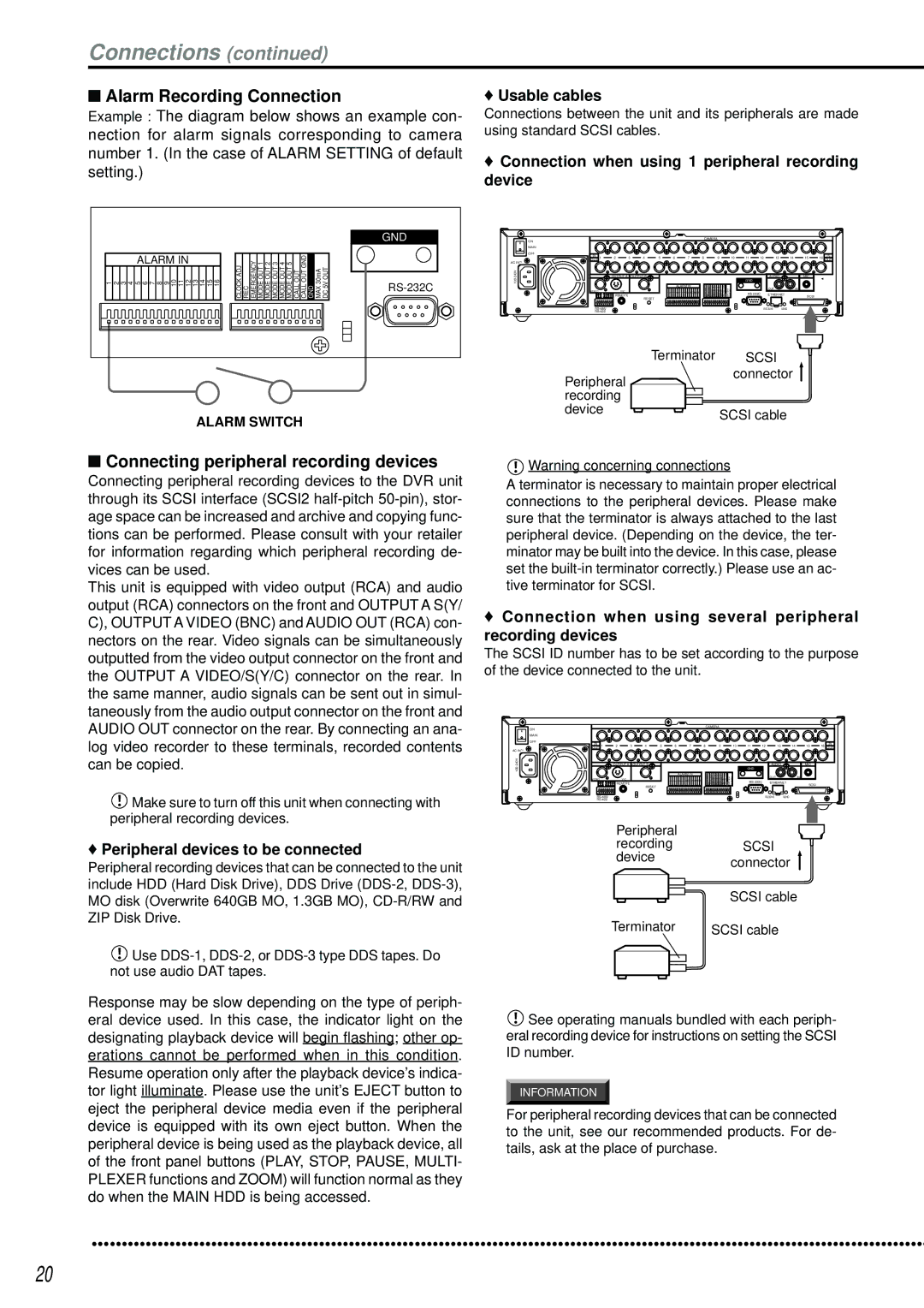
Connections
Connecting peripheral recording devices
Alarm Recording Connection
Connections
Perform Auto SET UP? is displayed on the screen
Connections /AUTO SET UP
Auto SET UP
Setting is confirmed and flashing stops
ID4ID5
Auto SET UP / Initial settings
When the setting is complete, press the Power button
Initialization
Setting of Boot UP Delay default 30S
Initial settings
HDD Setting
Boot UP Delay
RS-232C connector
Scsi connector
Ethernet connector
Basic Operations
Menu settings
Multiplexer functions
To return to the normal screen from a menu screen
Daylight SAVING/DAYLIGHT Setting
Default SUN, 1ST, APR
Time Date Adjust
Recorded capacity display function
Time is indicated using the 24-hour system
Basic Operations
Present time display
Shuttle ring clockwise as shown below
Screen see page 53, the REC mode settings are made
Timer Program Settings screen see
Basic manual recording
Back repeatedly see HDD Repeat PLAY,
Basic playback
Press the Play button
To stop playback, press the Stop button
Basic search
Time Date Search
To pause playback, press the Pause button
Press either the Play button or the Pause button
For playback, see Various playback func- tions, pages 73
Language Selection
To playback the searched image
Main Menu
Menu Setting
Menu functions
SUB Menu
Menu functions
SET UP
Operations
Main Menu SUB Menu
English JOG Select Shuttleexecute Language Selection
REC/STOP + Power button
Search Selection Menu
Copy Menu
Clock Location Setting
Time Date Adjust
Display Mode
Camera TITLE/MEMO Setting
Repeat steps 2 ~ 7 to input Counter in the camera number
Camera TITLE/MEMO Setting 1/2
Camera TITLE/MEMO Setting 2/2
Display returns to the Camera TITLE/MEMO Setting screen
Setting default Bottom
Duplex Mode Display
Available modes
Plexer can also be found on see
Camera number button operations
SPLIT/SEQUENCE button operations
Activated via the Alarm recording start flashing
Output B SPLIT4 Screen Setting screen
Is displayed using SPLIT4 display
Output B indicator illuminates
To set the multiplexer setting of the Output
MPX Display Settings
MPX Display Settings
SPLIT4 Screen Setting
Sequence Setting 1/2
SPLIT9 Screen Setting
SPLIT16 Screen Setting
Sequence Setting
Interlace
Sequence Setting 2/2
3 , 4 , 5 , 6 , 7 10 , 11 , 12 , 13
Button 15
Detection Mask Setting
& active setting changes to inactive setting
Selection Camera Number
Motion Threshold
Motion Detection Settings
Test Mode
Sensitivity
Alarm Setting 2/2
Settings concerning normal recording and alarm recording
Details concerning pre-alarm recording, see
Alarm Setting 1/2
Picture quality for normal recording pages 27
Record Settings
PRE Alarm REC
Pre-alarm recording can be set
Archive Overwrite
Alarm REC Duration
Recording time during alarm recording can be set
Motion DET REC
Timer Program screen appears
Timer Program Settings
Timer Program
Structure of the Timer Program screen
Background of the MD setting turns red and flashes
Press the Timer button
Background of the end day setting turns red and flashes
Background of the Mode setting turns red and flashes
Overlapping Timer settings
Timer Program Settings
Holiday Setting
Cerning recording mode settings, see pages 27, 28
IM-CHECK Play
HDD Settings HDD Repeat REC Main HDD Repeat REC SUB
Operation when HDD Hard Disk Drive space is full
HDD Repeat Play
Play see
Initial SET UP/INFORMATION
Archive Fifo Overwrite Mode
Sequential Play
Archive Source HDD
Archive Start Position Reset
Archive Start Position Reset screen is displayed
Archive Point is reset
Audio Recording
Rear Terminal Settings Mode OUT 1 ~ Mode OUT
KEY Sound
Remain HDD
Setting of Device default Main
Setting of Remain HDD default 10%
Buzzer
Emergency REC Duration
Communication Port Settings
Call OUT Settings
HDD Main REMAIN/HDD SUB REMAIN/ Archive Remain
Ethernet
Settings
RS-232C
Mode
Mail Address
Service Port Setting
Alarm Notification Setting
Setting of Warning default OFF
Setting of Retry Time default 10S
INFORMATION/SERVICE
Setting of Alarm Sens default OFF
Setting of REC Mode default OFF
ARCHIVE/COPY Information screen is displayed
HDD Information screen is displayed
Data Clear
Password
Reset to Factory Settings
Password Lock
Repeat steps 2-2 ~ 2-4 to set level 2
To register the Password
To unlock the Password
Input the Password entered in First in Second
Language Selection
To change the Password
Changing from Password Lock mode to Simple Lock mode
To lock the Password
To save menu settings of this unit to a Compact Flash Card
Quick Settings
This unit can save or load Menu settings stored
To update menu settings of this unit
Operation
Setting
Operation examples
Operation example
Operation examples
Timer Program screen setting see pages 50
This example uses the holiday setting
HDD Settings screen setting see pages
Emergency REC Duration 20M
Following day
Record Setting D screen setting see
REC Mode C screen setting see
REC Mode D screen setting see
Alarm Setting D screen setting see
Archive Archive Media Auto Eject
Record for 24HOURS
Emergency Recordings
PRE Alarm Recordings
Pre-alarm recording
Various recordings
Various playback functions
Simultaneous playback during recording
Monitor display settings and playback operation
Press the REV. Play Reverse Playback button
DATE/TIME
Various search
Search Selection
Search Type
See pages 29
Index SEARCH/ALARM Index Search
Various search
Time Date Search
Alarm Skip Search In the case of forward direction
Alarm Skip Search
Select the desired alarm list number
Alarm List Search
Press either the Play REV. Play or Pause button
Search screen selected in above Search Type appears
START/END Search
Copy screen appears
Making Copy/Restore
Display the desired setting in Mode and confirm
Display the desired setting in Transfer Period and confirm
Video Cord Audio Cord
Copy restore operation is executed
Copying from unit to videotape
See Sequential PLAY,
Other convenient functions
Power failure compensation circuit
Power failure reset recording
HDD Setting
Points to be aware of regarding Mirror mode
PARTITION/PARTITION Size
Points to be aware of regarding Partition mode
Partition Size setting appears on the Initialization screen
Other convenient functions
Covert Camera Setting 2/2
Covert Camera Setting
Alarm Display
Covert Camera Setting 1/2
Personal computer product requirements
Authentication
Communications by Web Browser
Communications by Web Browser
Select live monitor and left-click
Welcome
Live monitor
Select the desired Menu and left-click
Playback
Communications by Web Browser
Time Search
User maintenance
Alarm Search
Index Search
Change log in user
This screen, assign Log out settings to end the job
User
Log out
Logged in user is changed and the Welcome screen appears
Without Audio recording
Recording time table
Continuous recording time table
HDD continuous recording time for 240GB drive
Super
Compact Flash Card continuous recording time for 64MB
Description of problem Please consult the following
Troubleshooting
Others
ARCHIVE/FULL REC/REM
ARCHIVE/SIZE/ Data Error
System Error
Glossary
Glossary
Specifications
872C276A0