Memory Maps
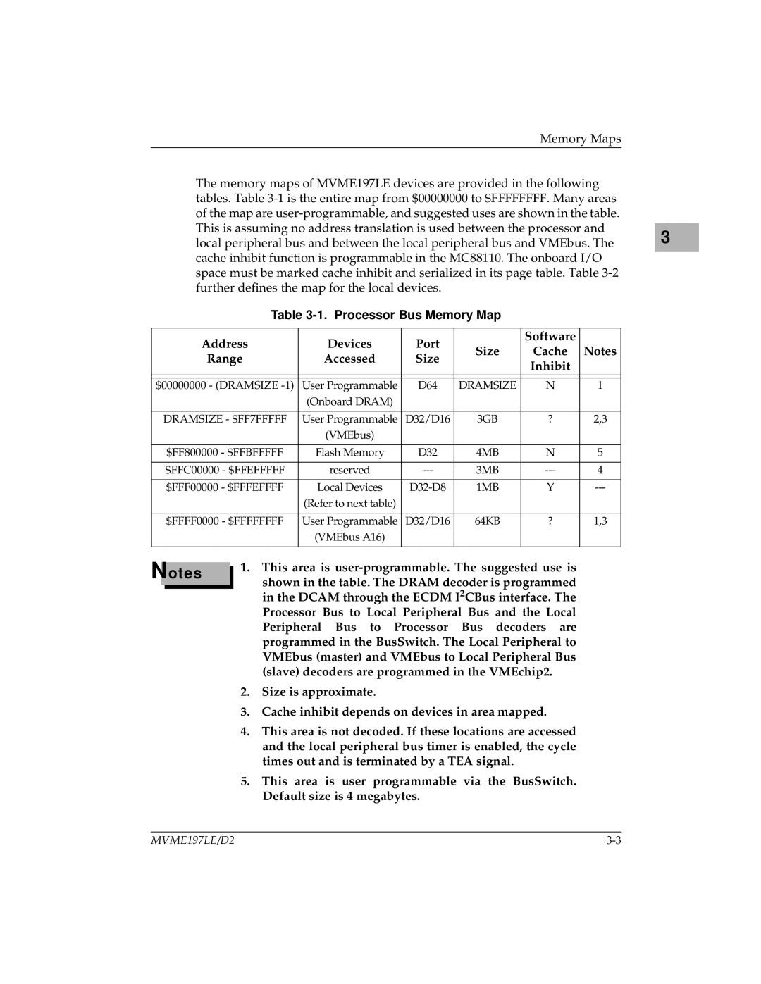
The memory maps of MVME197LE devices are provided in the following tables. Table
3 |
Table 3-1. Processor Bus Memory Map
Address | Devices | Port |
| Software |
| |
Size | Cache | Notes | ||||
Range | Accessed | Size | ||||
| Inhibit |
| ||||
|
|
|
|
| ||
|
|
|
|
|
| |
|
|
|
|
|
| |
$00000000 - (DRAMSIZE | User Programmable | D64 | DRAMSIZE | N | 1 | |
| (Onboard DRAM) |
|
|
|
| |
|
|
|
|
|
| |
DRAMSIZE - $FF7FFFFF | User Programmable | D32/D16 | 3GB | ? | 2,3 | |
| (VMEbus) |
|
|
|
| |
|
|
|
|
|
| |
$FF800000 - $FFBFFFFF | Flash Memory | D32 | 4MB | N | 5 | |
|
|
|
|
|
| |
$FFC00000 - $FFEFFFFF | reserved | 3MB | 4 | |||
|
|
|
|
|
| |
$FFF00000 - $FFFEFFFF | Local Devices | 1MB | Y | |||
| (Refer to next table) |
|
|
|
| |
|
|
|
|
|
| |
$FFFF0000 - $FFFFFFFF | User Programmable | D32/D16 | 64KB | ? | 1,3 | |
| (VMEbus A16) |
|
|
|
| |
|
|
|
|
|
|
Notes
1.This area is
shown in the table. The DRAM decoder is programmed in the DCAM through the ECDM I2CBus interface. The Processor Bus to Local Peripheral Bus and the Local Peripheral Bus to Processor Bus decoders are programmed in the BusSwitch. The Local Peripheral to VMEbus (master) and VMEbus to Local Peripheral Bus (slave) decoders are programmed in the VMEchip2.
2.Size is approximate.
3.Cache inhibit depends on devices in area mapped.
4.This area is not decoded. If these locations are accessed and the local peripheral bus timer is enabled, the cycle times out and is terminated by a TEA signal.
5.This area is user programmable via the BusSwitch. Default size is 4 megabytes.
MVME197LE/D2 |
