A
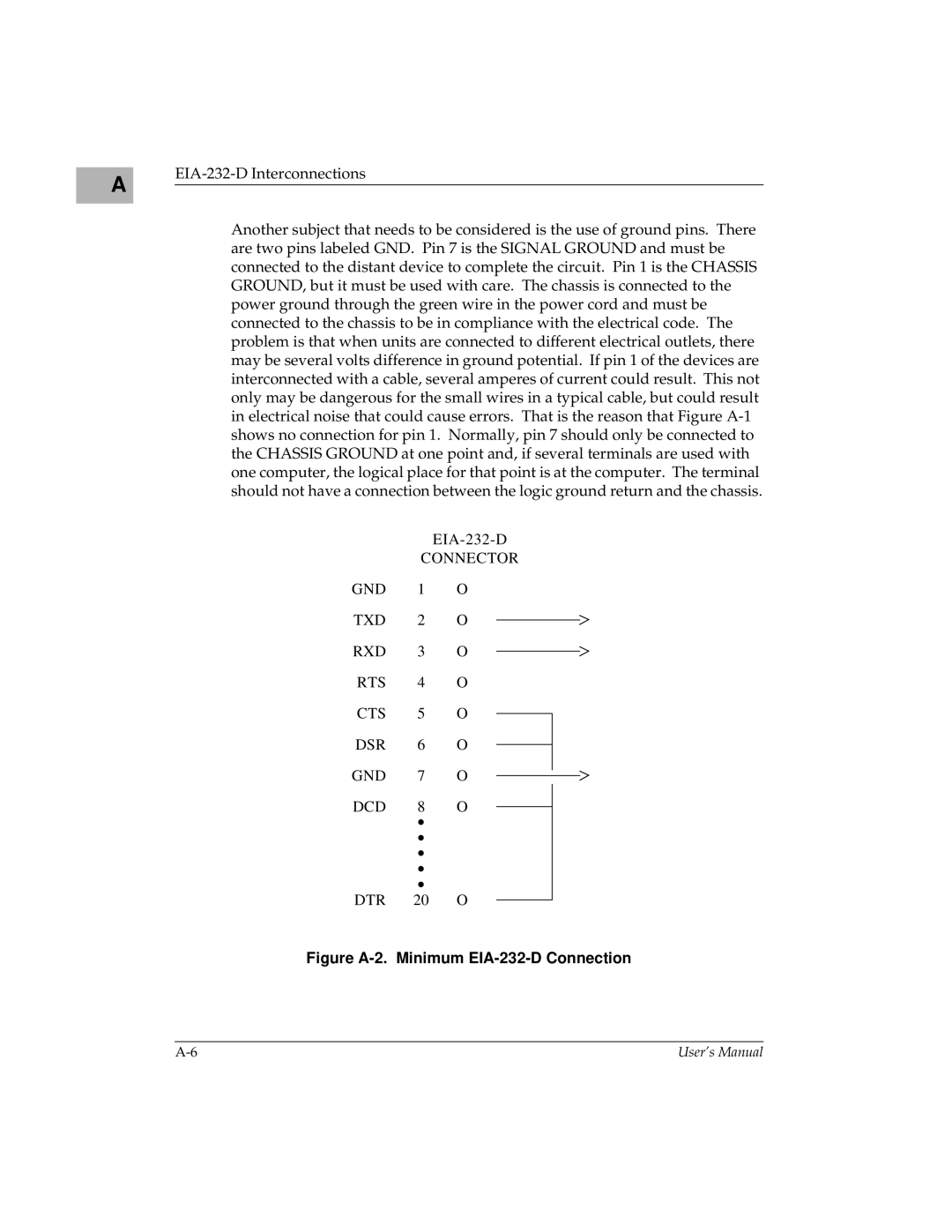
Another subject that needs to be considered is the use of ground pins. There are two pins labeled GND. Pin 7 is the SIGNAL GROUND and must be connected to the distant device to complete the circuit. Pin 1 is the CHASSIS GROUND, but it must be used with care. The chassis is connected to the power ground through the green wire in the power cord and must be connected to the chassis to be in compliance with the electrical code. The problem is that when units are connected to different electrical outlets, there may be several volts difference in ground potential. If pin 1 of the devices are interconnected with a cable, several amperes of current could result. This not only may be dangerous for the small wires in a typical cable, but could result in electrical noise that could cause errors. That is the reason that Figure
CONNECTOR
GND | 1 | O |
TXD | 2 | O |
RXD | 3 | O |
RTS | 4 | O |
CTS | 5 | O |
DSR | 6 | O |
GND | 7 | O |
DCD | 8 | O |
| ∙ |
|
| ∙ |
|
| ∙ |
|
| ∙ |
|
| ∙ |
|
DTR | 20 | O |
Figure A-2. Minimum EIA-232-D Connection
User’s Manual |