|
| ||
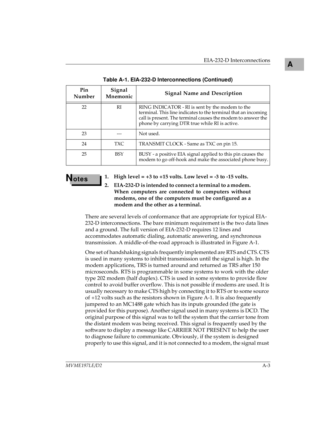
| Table | ||
|
|
| |
Pin | Signal | Signal Name and Description | |
Number | Mnemonic | ||
| |||
|
|
| |
|
|
| |
22 | RI | RING INDICATOR - RI is sent by the modem to the | |
|
| terminal. This line indicates to the terminal that an incoming | |
|
| call is present. The terminal causes the modem to answer the | |
|
| phone by carrying DTR true while RI is active. | |
|
|
| |
23 | Not used. | ||
|
|
| |
24 | TXC | TRANSMIT CLOCK - Same as TXC on pin 15. | |
|
|
| |
25 | BSY | BUSY - a positive EIA signal applied to this pin causes the | |
|
| modem to go | |
|
|
| |
A |
Notes
1.High level = +3 to +15 volts. Low level =
2.
There are several levels of conformance that are appropriate for typical EIA-
One set of handshaking signals frequently implemented are RTS and CTS. CTS is used in many systems to inhibit transmission until the signal is high. In the modem applications, TRS is turned around and returned as TRS after 150 microseconds. RTS is programmable in some systems to work with the older type 202 modem (half duplex). CTS is used in some systems to provide flow control to avoid buffer overflow. This is not possible if modems are used. It is usually necessary to make CTS high by connecting it to RTS or to some source of +12 volts such as the resistors shown in Figure
MVME197LE/D2 |