Data and address sizes are defined as follows:
❏A byte is eight bits, numbered 0 through 7, with bit 0 being the least significant.
❏A
❏A
❏An
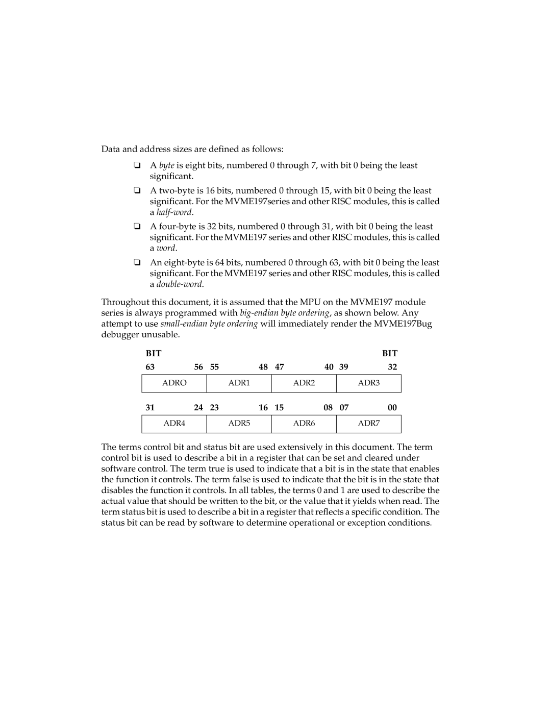
Throughout this document, it is assumed that the MPU on the MVME197 module series is always programmed with
BIT |
|
|
|
|
|
| BIT |
63 | 56 | 55 | 48 | 47 | 40 | 39 | 32 |
|
|
|
|
|
|
|
|
ADRO |
| ADR1 |
| ADR2 |
|
| ADR3 |
|
|
|
|
|
|
|
|
31 | 24 | 23 | 16 | 15 | 08 | 07 | 00 |
|
|
|
|
|
|
|
|
ADR4 |
| ADR5 |
| ADR6 |
|
| ADR7 |
|
|
|
|
|
|
|
|
The terms control bit and status bit are used extensively in this document. The term control bit is used to describe a bit in a register that can be set and cleared under software control. The term true is used to indicate that a bit is in the state that enables the function it controls. The term false is used to indicate that the bit is in the state that disables the function it controls. In all tables, the terms 0 and 1 are used to describe the actual value that should be written to the bit, or the value that it yields when read. The term status bit is used to describe a bit in a register that reflects a specific condition. The status bit can be read by software to determine operational or exception conditions.