general information

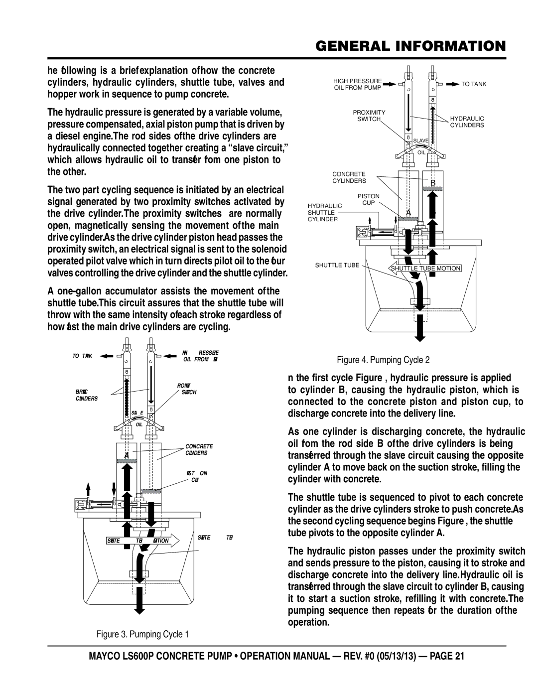
he following is a brief explanation of how the concrete cylinders, hydraulic cylinders, shuttle tube, valves and hopper work in sequence to pump concrete.

The hydraulic pressure is generated by a variable volume, pressure compensated, axial piston pump that is driven by a diesel engine. The rod sides of the drive cylinders are hydraulically connected together creating a “slave circuit,” which allows hydraulic oil to transfer from one piston to the other.

The two part cycling sequence is initiated by an electrical signal generated by two proximity switches activated by

HIGH PRESSURE OIL FROM PUMP

PROXIMITY

SWITCH

CONCRETE

CYLINDERS

PISTON

TO TANK

HYDRAULIC

CYLINDERS

SLAVE

OIL

B

the drive cylinder. The proximity switches are normally open, magnetically sensing the movement of the main drive cylinder. As the drive cylinder piston head passes the proximity switch, an electrical signal is sent to the solenoid operated pilot valve which in turn directs pilot oil to the four

HYDRAULIC SHUTTLE CYLINDER

CUP

A

B

valves controlling the drive cylinder and the shuttle cylinder.

Aone-gallon accumulator assists the movement of the shuttle tube. This circuit assures that the shuttle tube will throw with the same intensity of each stroke regardless of how fast the main drive cylinders are cycling.

SHUTTLE TUBE

SHUTTLE TUBE MOTION

TO TANK

HYDRAULIC

CYLINDERS

SLAVE

OIL

A

B

HIGH PRESSURE OIL FROM PUMP

PROXIMITY

SWITCH

CONCRETE

CYLINDERS

PISTON

CUP

Figure 4. Pumping Cycle 2

In the first cycle (Figure 3), hydraulic pressure is applied to cylinder (B), causing the hydraulic piston, which is connected to the concrete piston and piston cup, to discharge concrete into the delivery line.

As one cylinder is discharging concrete, the hydraulic oil from the rod side (B) of the drive cylinders is being transferred through the slave circuit causing the opposite cylinder (A) to move back on the suction stroke, filling the cylinder with concrete.

The shuttle tube is sequenced to pivot to each concrete cylinder as the drive cylinders stroke to push concrete. As the second cycling sequence begins (Figure 4), the shuttle tube pivots to the opposite cylinder (A).

SHUTTLE TUBE MOTION

SHUTTLE TUBE

The hydraulic piston passes under the proximity switch and sends pressure to the piston, causing it to stroke and discharge concrete into the delivery line. Hydraulic oil is transferred through the slave circuit to cylinder B, causing it to start a suction stroke, refilling it with concrete. The pumping sequence then repeats for the duration of the operation.

Figure 3. Pumping Cycle 1

MAYCO LS600P CONCRETE PUMP • operation manual — rev. #0 (05/13/13) — page 21

Page 21
Image 21
Multiquip LS600P operation manual Pumping Cycle

LS600P specifications

The Multiquip LS600P is an innovative solution in the realm of construction machinery, designed to meet the demanding needs of modern job sites. This versatile piece of equipment is particularly noteworthy for its performance capabilities, fuel efficiency, and user-friendly design, making it an essential addition for contractors seeking reliability and efficiency.

One of the standout features of the LS600P is its powerful engine, which delivers robust performance while minimizing fuel consumption. This results in lower operating costs, enabling contractors to maximize their investment. The LS600P is equipped with a dependable and environmentally friendly engine, compliant with emission standards, thus contributing to sustainable operations on job sites.

The machine is designed with a focus on ease of use and operator comfort. Its intuitive control panel allows for straightforward operation, reducing the learning curve and enabling operators to become proficient quickly. Additionally, the ergonomic design of the operator's platform provides comfort during long hours of operation, enhancing productivity and reducing fatigue.

In terms of versatility, the LS600P can be utilized for a variety of applications. Whether it is compaction for paving projects, soil stabilization, or site preparation, its multi-functional capabilities make it suitable for diverse construction tasks. This adaptability is further enhanced by its compatibility with various attachments, allowing contractors to customize the machine to meet specific project requirements.

The durability of the LS600P is another key characteristic. Built with high-quality materials and components, it is engineered to withstand the harsh conditions often encountered on construction sites. This durability, combined with easy maintenance features, ensures that the Multiquip LS600P will provide reliable service over its operational lifespan.

Incorporating advanced technologies, the LS600P features an efficient hydraulic system that enhances its performance and responsiveness. This hydraulic system not only improves the effectiveness of its functions but also contributes to energy efficiency, thus promoting greener operations.

In conclusion, the Multiquip LS600P is a high-performance, efficient, and versatile machine. With features focused on user comfort, operational efficiency, and adaptability for various tasks, it stands out as a reliable choice for contractors aiming to enhance productivity and project outcomes on their construction sites.