Part Names and Functions
Front View
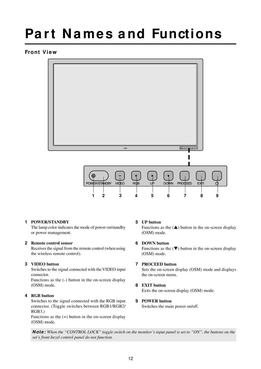
1 | 2 | 3 | 4 | 5 | 6 | 7 | 8 | 9 |
1POWER/STANDBY
The lamp color indicates the mode of power on/standby or power management.
2Remote control sensor
Receives the signal from the remote control (when using the wireless remote control).
3VIDEO button
Switches to the signal connected with the VIDEO input connector.
Functions as the
4RGB button
Switches to the signal connected with the RGB input connector. (Toggle switches between RGB1/RGB2/ RGB3.)
Functions as the (+) button in the
5UP button
Functions as the (▲) button in the
6DOWN button
Functions as the (▼) button in the
7PROCEED button
Sets the
8EXIT button
Exits the
9POWER button
Switches the main power on/off.
Note: When the “CONTROL LOCK” toggle switch on the monitor’s input panel is set to “ON”, the buttons on the set’s front bezel control panel do not function.
12
