Function and Pin Configuration of the External Control Connector
Application
These specifications are applicable to NEC plasma monitors (including 42- and
Connections
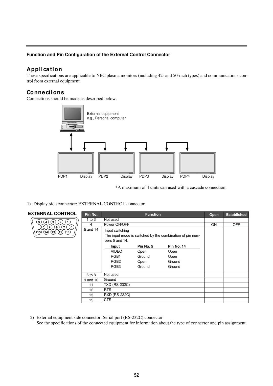
Connections should be made as described below.
External equipment e.g., Personal computer
PDP1 | Display PDP2 | Display PDP3 | Display PDP4 | Display |
*A maximum of 4 units can used with a cascade connection.
1)
EXTERNAL CONTROL | Pin No. | Function | Open | Established | ||||||
5 |
| 4 | 3 | 2 | 1 | 1 to 3 | Not used |
|
| |
| 4 | Power ON/OFF | ON | OFF | ||||||
10 | 9 | 8 | 7 | 6 | ||||||
5 and 14 | Input switching |
|
| |||||||
15 | 14 | 13 | 12 | 11 |
|
| ||||
| The input mode is switched by the combination of pin num- |
|
| |||||||
|
|
|
|
|
|
|
|
| ||
|
|
|
|
|
|
| bers 5 and 14. |
|
| |
|
| Input | Pin No. 5 | Pin No. 14 |
|
|
| VIDEO | Open | Open | |
|
| RGB1 | Ground | Open | |
|
| RGB2 | Open | Ground | |
|
| RGB3 | Ground | Ground | |
|
|
|
|
|
|
6 to 8 | Not used |
|
|
| |
9 and 10 | Ground |
|
|
| |
11 | TXD |
|
|
| |
12 | RTS |
|
|
| |
13 | RXD |
|
|
| |
15 | CTS |
|
|
| |
2)External equipment side connector: Serial port
See the specifications of the connected equipment for information about the type of connector and pin assignment.
52