Side View.... Terminal Board L/R
10
11
12
13
14
Insert the prongs completely.
* for PLUGGABLE EQUIPMENT, tee
equipment and shall be easily accessible.
OUT | IN |
| VIDEO |
| |
| 75Ω |
| HIGH |
| V |
| H/CS |
| B |
| G |
| R |
| RGB2 |
RGB1 |
|
|
15
16
17
18
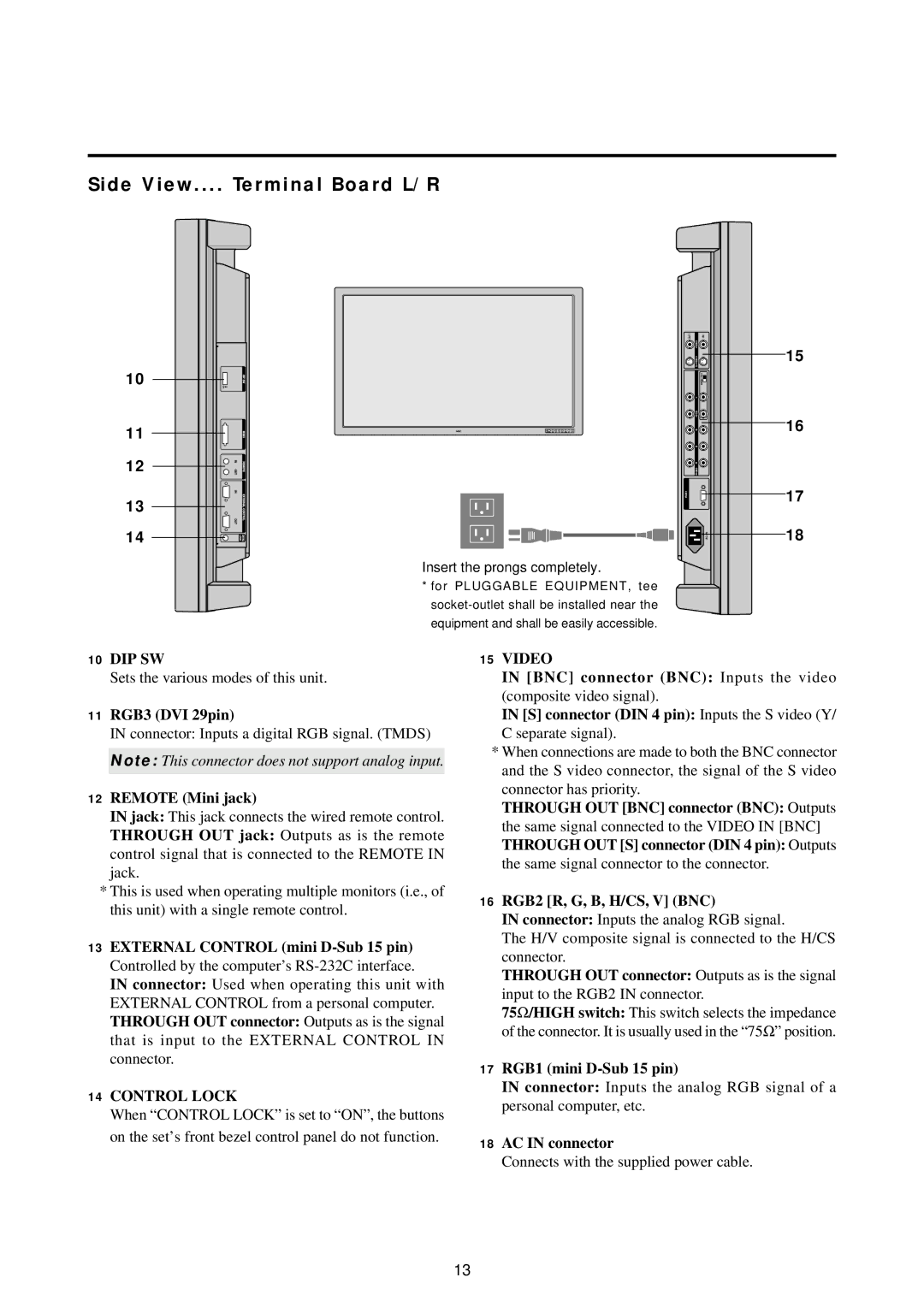
10DIP SW
Sets the various modes of this unit.
11RGB3 (DVI 29pin)
IN connector: Inputs a digital RGB signal. (TMDS)
Note: This connector does not support analog input.
12REMOTE (Mini jack)
IN jack: This jack connects the wired remote control.
THROUGH OUT jack: Outputs as is the remote control signal that is connected to the REMOTE IN jack.
*This is used when operating multiple monitors (i.e., of this unit) with a single remote control.
13EXTERNAL CONTROL (mini
IN connector: Used when operating this unit with EXTERNAL CONTROL from a personal computer. THROUGH OUT connector: Outputs as is the signal that is input to the EXTERNAL CONTROL IN connector.
14CONTROL LOCK
When “CONTROL LOCK” is set to “ON”, the buttons on the set’s front bezel control panel do not function.
15VIDEO
IN [BNC] connector (BNC): Inputs the video (composite video signal).
IN [S] connector (DIN 4 pin): Inputs the S video (Y/ C separate signal).
*When connections are made to both the BNC connector and the S video connector, the signal of the S video connector has priority.
THROUGH OUT [BNC] connector (BNC): Outputs the same signal connected to the VIDEO IN [BNC] THROUGH OUT [S] connector (DIN 4 pin): Outputs the same signal connector to the connector.
16RGB2 [R, G, B, H/CS, V] (BNC)
IN connector: Inputs the analog RGB signal.
The H/V composite signal is connected to the H/CS connector.
THROUGH OUT connector: Outputs as is the signal
input to the RGB2 IN connector.
75Ω/HIGH switch: This switch selects the impedance of the connector. It is usually used in the “75 Ω” position.
17RGB1 (mini D-Sub 15 pin)
IN connector: Inputs the analog RGB signal of a personal computer, etc.
18AC IN connector
Connects with the supplied power cable.
13