To Reset the Adjustment Value to the Factory Default Setting
1.Press the VISUAL NORMAL button or RASTER NORMAL button.
The verification sub menu is displayed.
VISUALRASTER
NORMALNORMAL
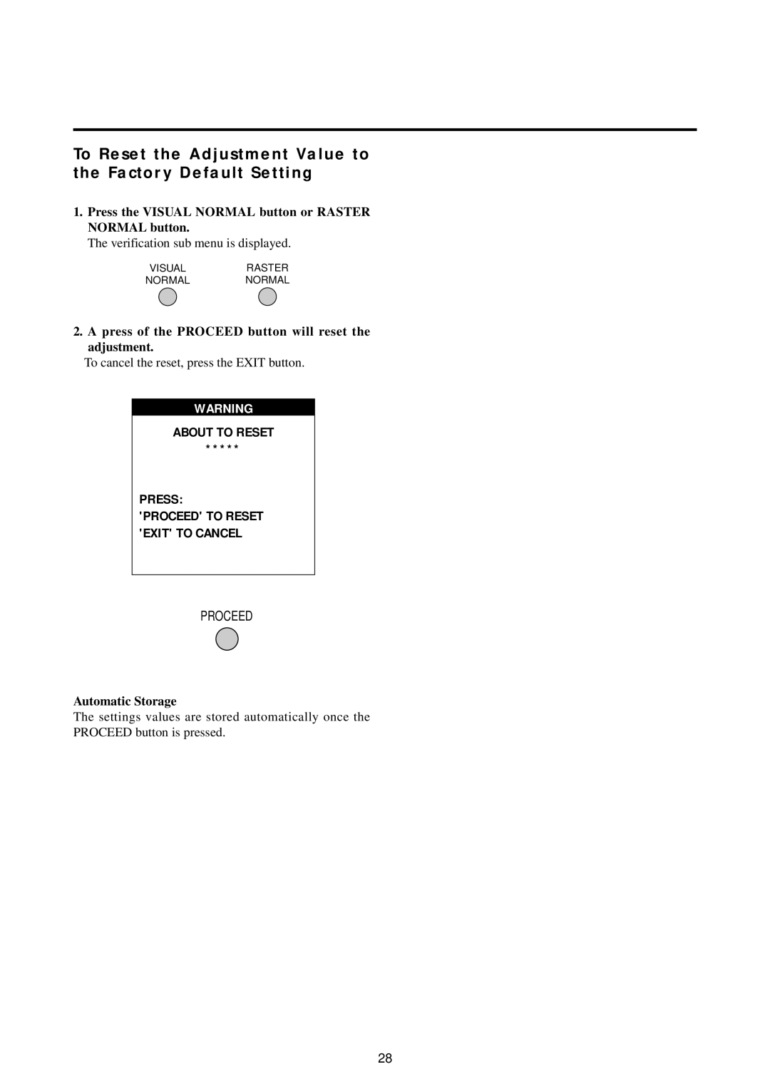
2.A press of the PROCEED button will reset the adjustment.
To cancel the reset, press the EXIT button.
WARNING
ABOUT TO RESET
*****
PRESS:
'PROCEED' TO RESET 'EXIT' TO CANCEL
PROCEED
Automatic Storage
The settings values are stored automatically once the PROCEED button is pressed.
28